
Bending beam load cell with torque sensitivity compensation

a technology of torque sensitivity compensation and load cell, which is applied in the direction of force measurement, force/torque/work measurement apparatus, instruments, etc., can solve the problems of small differences in the strain sensitivity of the four strain gages, small mechanical differences in the bending beam, and errors in the position of the gages on the bending beam

Inactive Publication Date: 2005-06-28
FLINTEC GROUP
View PDF20 Cites 28 Cited by
  • Summary
  • Abstract
  • Description
  • Claims
  • Application Information

AI Technical Summary

Benefits of technology

[0012]An aspect of the present invention is to provide a bending beam load cell that can be compensated for torque sensitivity by purely electrical means.
[0013]Another aspect of the present invention is to provide a bending beam load cell that can be hermetically sealed before front-to-back and side-to-side off center load errors are compensated.

Problems solved by technology

In practice, there are small differences in the strain sensitivity of the four strain gages, and small mechanical differences in the bending beams, as well as errors in the position of the gages on the bending beams.
These errors upset the symmetry of the load cell, so there will be errors in the output signal caused by movement of the load application point, both along the load cell axis (“Front-to-back off center load error”), and crosswise to the load cell axis (“Side-to-side off center load error”).
The filing requires great skill, and it is time consuming, but it is still the most used method for compensation of off center load errors in single point load cells.
A serious disadvantage with filing of the bending beams to compensate for torque sensitivity is that it makes it impossible to seal the load cell.
Filing, however, can not be done after the bellows is in place.
U.S. Pat. No. 3,576,128 to Lockery describes an effective method for electrical compensation of the front-to-back off center load error, but it is not applicable to compensation of torque sensitivity.
The compensation procedure described in the referenced patent is very complicated.
This method is quite complicated, and requires nonstandard electronic instruments for display of load signals.
It has not been successfully used commercially.

Method used


Image

  • Bending beam load cell with torque sensitivity compensation
  • Bending beam load cell with torque sensitivity compensation
  • Bending beam load cell with torque sensitivity compensation

Examples


Embodiment Construction

[0028]Reference will now be made in detail to the embodiments of the present invention, examples of which are illustrated in the accompanying drawings, wherein like reference numerals refer to like elements throughout. The embodiments are described below in order to explain the present invention by referring to the figures.

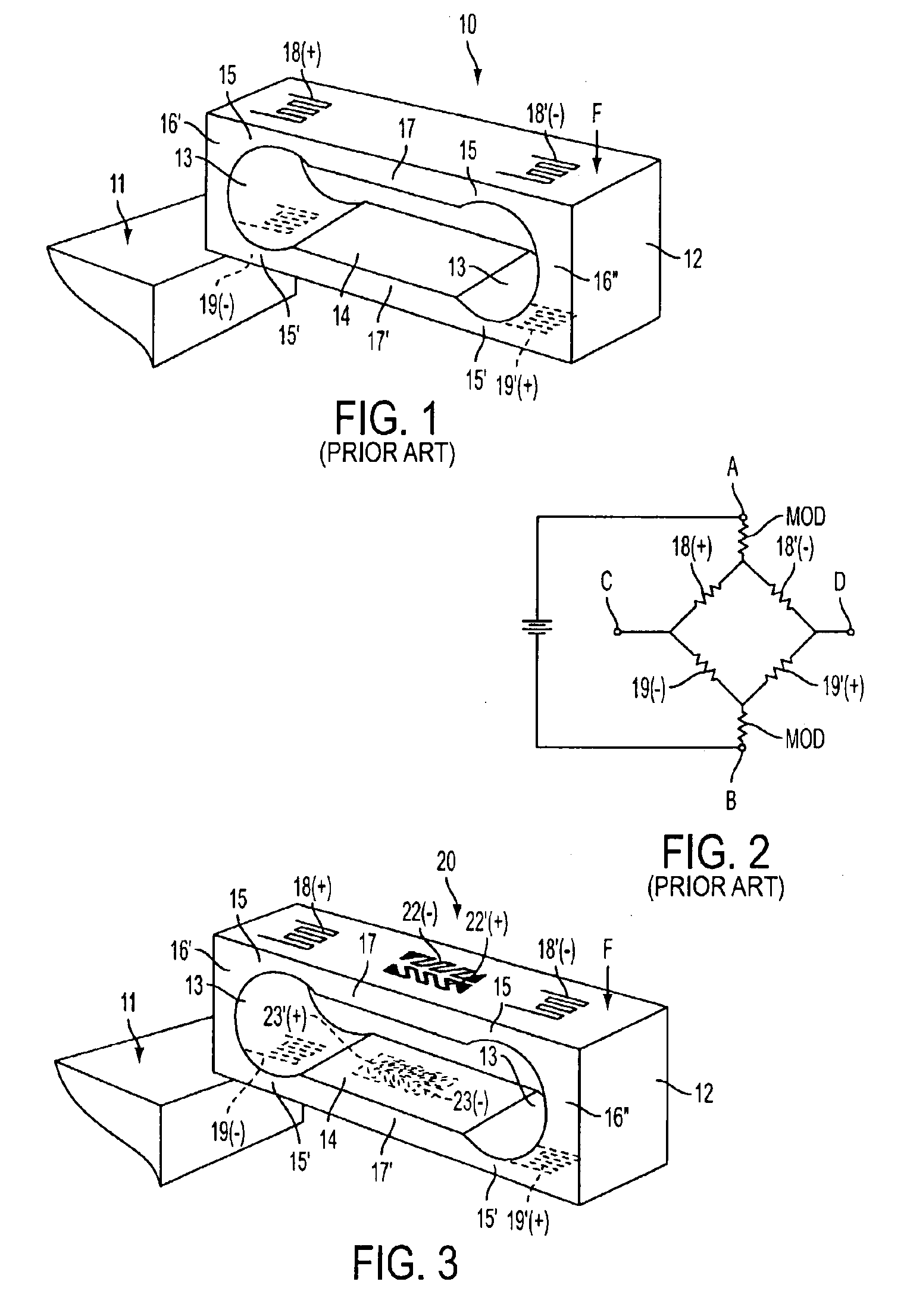
[0029]Compensation for torque sensitivity according to embodiments of the invention is best understood by comparison with a prior art load cell, which is shown in FIGS. 1 and 2.

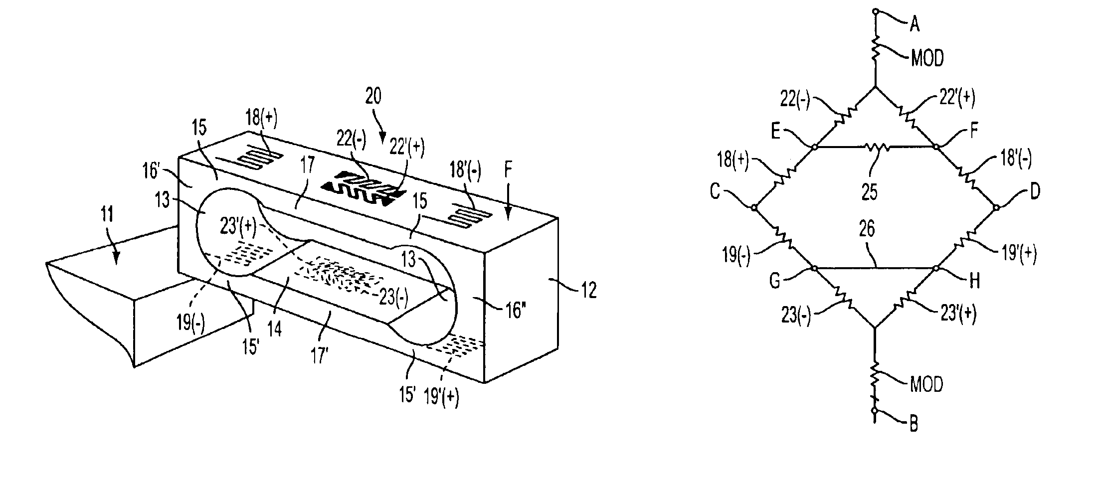
[0030]FIG. 1 is a simplified perspective view of a single point load cell 10, which is cantilevered from a base 11. The load cell is made from a block 12 of load cell quality metal alloy. Two transverse cylindrical cutouts 13 are joined by a longitudinal slot 14 to form a pair of bending beams 17, 17′ held in fixed parallel relationship by end blocks 16′ and 16″. The cylindrical cutouts 13 form a pair of thin flexures 15 and 15′ between the bending beams 17, 17′ and the end blocks 16′, 16″....


PUM

PropertyMeasurementUnit
resistanceaaaaaaaaaa
tensionaaaaaaaaaa

Abstract

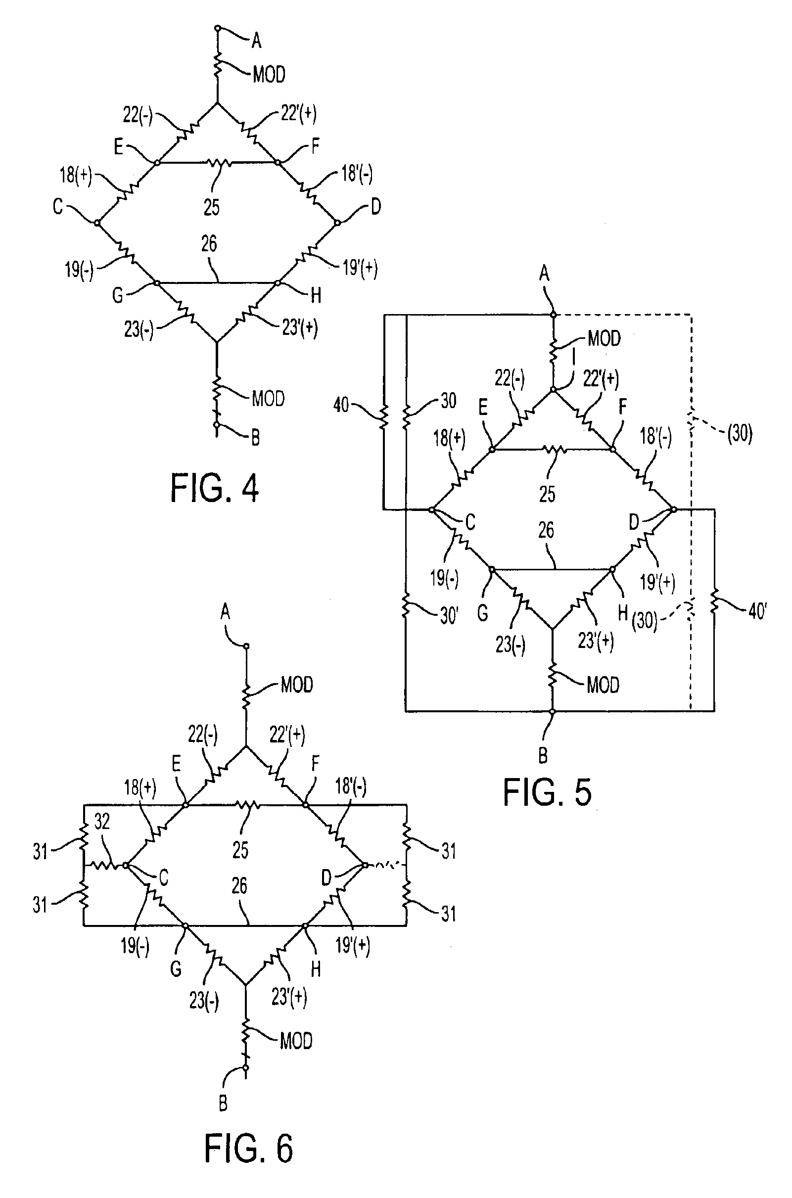
A bending beam load cell can be compensated for side-to-side off center load sensitivity by simple electrical adjustments if a pair of shear sensing strain gages are bonded to each bending beam midway between axial strain gages used to measure bending strains. The shear sensing strain gages measure torque on the load cell, and are incorporated in bridge circuits that make it possible to vary the amount of torque sensitivity correction by changing the value of a trimming resistor. The bridge circuits also include circuit components for compensation of front-to-back off center load error and for zero adjustment. Four strain gages on each bending beam can be part of a single composite strain gage element, so the shear sensing strain gages do not add any cost to the load cell. Such a load cell can also be hermetically sealed before any compensation of offset load errors is done.

Description

BACKGROUND OF THE INVENTION[0001]1. Field of the Invention[0002]The present invention relates to strain gage load cells, and more particularly to bending beam load cells with means for eliminating errors caused by off center loading on the bending beam load cells.[0003]2. Description of the Related Art[0004]Bending beam load cells have been extensively used for weighing since about 1950. A common design is the Single Point Load Cell, which comprises two parallel bending beams on top of each other, separated by rigid end blocks. The load cell is cantilevered from a base supporting one end block, and the other end block supporting a load platform. Axially oriented strain gages are bonded to each beam near the joints with the end blocks.[0005]When a load acts on the load platform, the rigid end pieces force the two bending beams to flex into flat S-shapes. One strain gage on each bending beam will accordingly sense tension, while the second strain gage will sense compression. The four ...

Claims


Application Information

Patent Timeline
Patent Type & Authority Patents(United States)
IPC IPC(8): G01G3/14G01G3/00
CPCG01G3/1414G01G3/1412
Inventor LOCKERY, HARRY E.GRAY, ROBERT L.
Owner FLINTEC GROUP
Learn More