
Airway treatment apparatus with bias line cancellation

Inactive Publication Date: 2005-06-28
HILL ROM SERVICES
View PDF72 Cites 49 Cited by
  • Summary
  • Abstract
  • Description
  • Claims
  • Application Information

AI Technical Summary

Benefits of technology

[0010]The invention is a method and apparatus for clearing a patient's lungs of mucus. An oscillating compressive force is applied to the patient's chest that includes a steady stat

Problems solved by technology

The ABI Vest Airway Clearance System is effective in clearing. airways of mucus, however, there are limitations of its performance.
This can cause particular problems with some disease states.
External pressure on the chest of a COPD patient during inspiration may cause considerable distress.
Also, asthmatics may find the constant vest pressure extremely irritating, and those with constricted and inflamed airways may find it uncomfortable.
It is difficult to determine a short term reduction in airway resistance during treatment.
Prior art vest systems do not have the ability to aid in removing mucus from the upper airway passages.
The effectiveness of the treatment is greatly reduced if a weakened individual is unable to do this.

Method used


Image

  • Airway treatment apparatus with bias line cancellation
  • Airway treatment apparatus with bias line cancellation
  • Airway treatment apparatus with bias line cancellation

Examples


first embodiment (fig.1)

FIRST EMBODIMENT (FIG. 1)

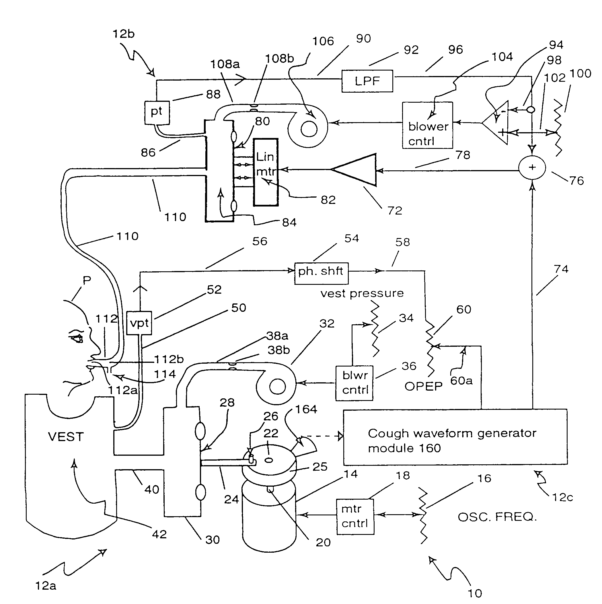
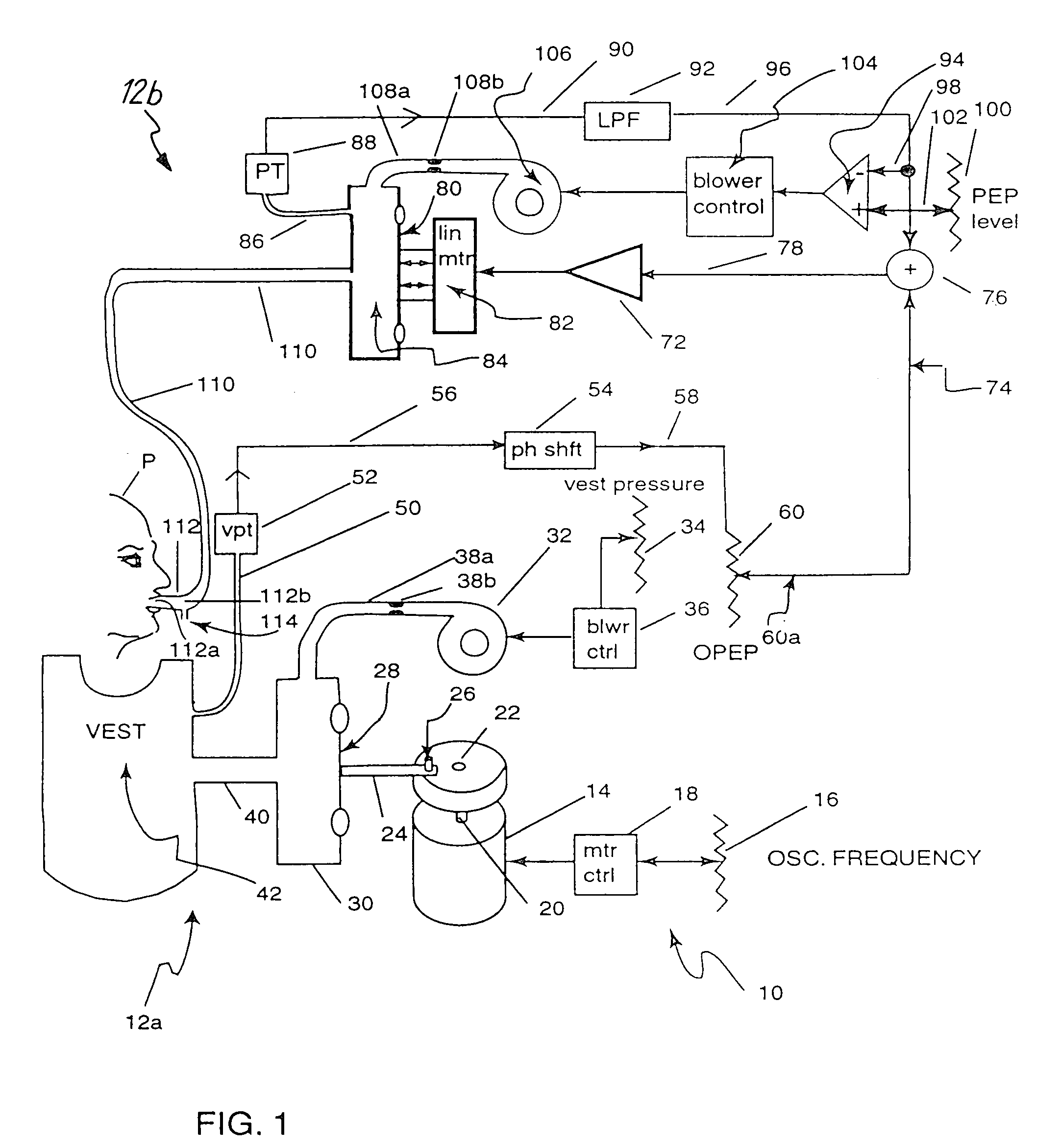
[0023]FIG. 1 is a block diagram showing a patient P undergoing treatment using the preferred embodiment of airway treatment apparatus 10. As shown in FIG. 1, apparatus 10 has two major subsystems, chest wall force applicator 12a (which applies oscillating compressive force to the chest of patient P) and air pressure input mouthpiece system 12b (which supplies air pressure to the patient's mouth in a relationship to the compressive force).

[0024]Chest wall force applicator 12a includes brushless motor 14, vest oscillation frequency potentiometer 16, motor controller 18, shaft 20, wheel 22, reciprocating arm 24, pin 26, diaphragm 28, air chamber 30, blower 32, vest pressure potentiometer 34, blower controller 36, tube 38a with constriction 38b, hoses 40, and inflatable vest 42. Oscillated air pressure is delivered to inflatable vest 42 to cause inflatable vest 42 to apply an oscillating force to the patient's chest.

[0025]Brushless motor 14 is operated by motor ...

second embodiment (

FIGS. 2–4B)

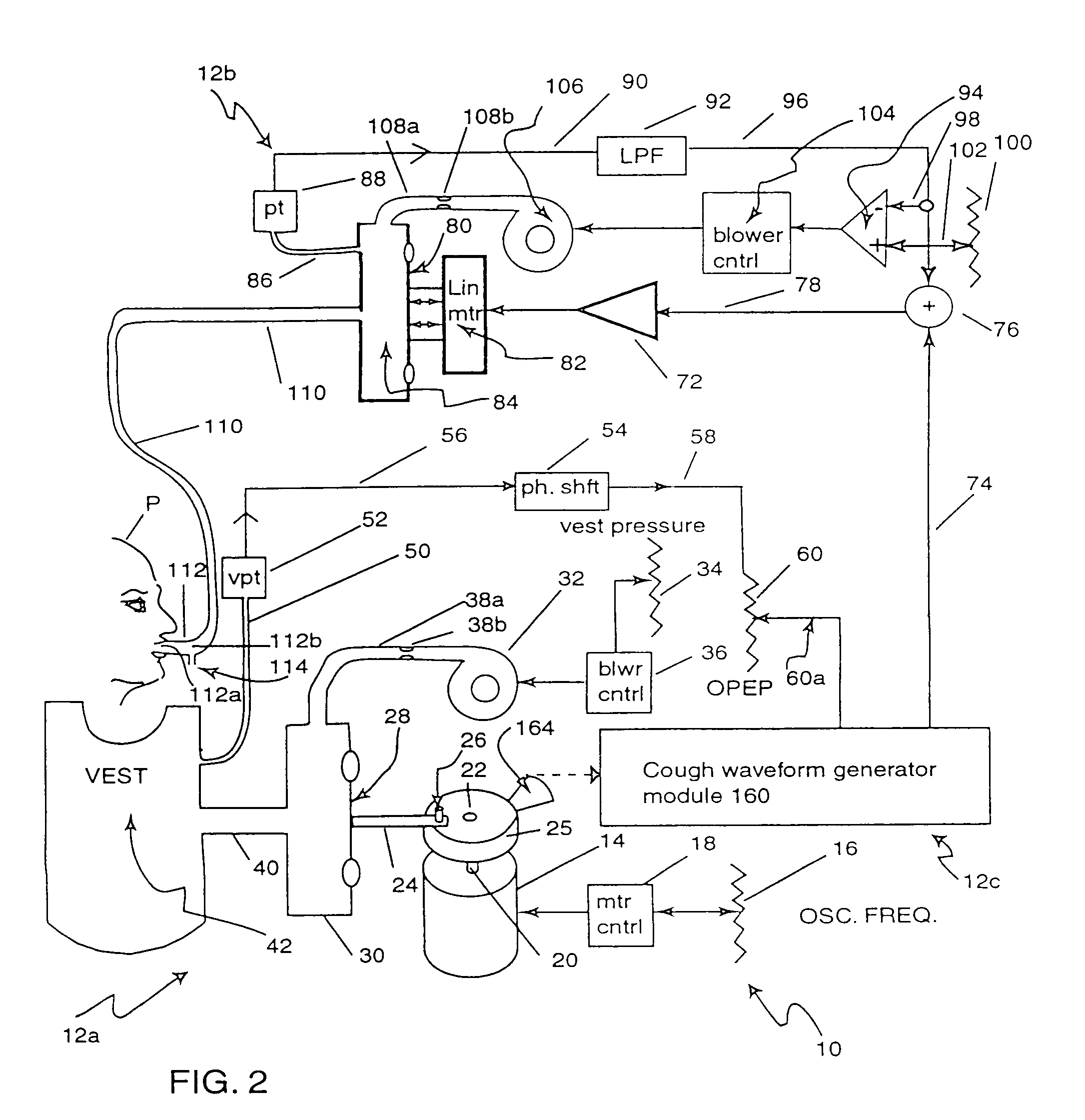
[0042]FIG. 2 shows a second embodiment of apparatus 10, having a simulated cough inducer 12c, which includes cough waveform generator module 160 and light interrupter 164. The embodiment shown in FIG. 2 is generally similar to the embodiment of FIG. 1, and similar reference characters are used to designate similar elements. FIG. 3 shows a schematic block diagram of cough waveform generator module 160, which includes optical sensor processor 166, cough waveform generator 168, line 170, cough intensity potentiometer 172, line 174, and summing junction 176.

[0043]Light interrupter 164 (FIG. 2) is attached to wheel 22 and sends signals to optical sensor processor 166. These components make up a diaphragm position sensor which is connected to cough waveform generator 168 via line 170. The output of cough waveform generator 168 is connected to Cough Intensity potentiometer 172. Line 174 connects Cough Intensity potentiometer 172 with one input of summing junction 176. Another in...

third embodiment (figs.5 – 8c)

THIRD EMBODIMENT (FIGS. 5–8C)

[0050]FIG. 5 shows a third embodiment of apparatus 10 which further includes airway resistance indicator 12d. The embodiment shown in FIG. 5 is generally similar to the embodiment shown in FIG. 1, and similar reference characters are used to designate similar elements. Airway resistance indicator 12d includes airway resistance module 200 (shown in FIG. 6), airway resistance null. detector / indicator module 210 (shown in FIG. 7) and test switch 220 (having terminals 220a–220c).

[0051]Airway resistance module 200 (FIG. 6) includes vest pressure transducer 52, phase shift network 54, lines 56 and 58, and PFT potentiometer 230, and lines 232 and 234. Vest pressure transducer 52 is linked to inflatable vest 42 by vest sampling tube 50. Phase shift network 54 is coupled to vest pressure transducer 52 via line 56. Line 58 connects phase shift network 54 with PFT potentiometer 230, which is connected to terminal 220a of test switch 220 by line 232. Line 234 couple...


PUM


Abstract

An airway clearance system and method produces high frequency chest wall oscillations (HFCWO) and increased airflow velocities through the air passages to clear the lungs of mucus. The system includes a chest wall force applicator to produce the HFCWO by applying an oscillating force component and a steady state (or bias line) force component. An air pressure input mouthpiece system that supplies airflow to a mouthpiece with a steady state, air component which tends to counteract or cancel the bias line force component.

Description

CROSS-REFERENCE TO RELATED APPLICATION(S)[0001]Reference is made to the following applications which are filed on even date and assigned to the same assignee as this application: AIRWAY TREATMENT APPARATUS WITH AIRFLOW ENHANCEMENT, Ser. No. 09 / 412,768, now U.S. Pat. No. 6,340,025; AIRWAY TREATMENT APPARATUS WITH COUGH INDUCEMENT, Ser. No. 09 / 412,457, now U.S. Pat. No. 6,415,791; and OUTCOME MEASURING AIRWAY RESISTANCE DIAGNOSTIC SYSTEM, Ser. No. 09 / 412,086, now U.S. Pat. No. 6,210,345.BACKGROUND OF THE INVENTION[0002]The present invention relates to an airway clearance system and in particular to a system that includes a chest compression device for high frequency chest wall oscillation and a subsystem which cancels bias line pressure and enhances airflow velocity through the air passages caused by the high frequency chest wall oscillations.[0003]Chest compression devices have been developed to produce high frequency chest wall oscillation (HFCWO). HFCWO is the most successful metho...

Claims


Application Information

Patent Timeline
IPC IPC(8): A61H23/04A61B5/08A61B5/085A61M16/00A61H31/00A61M16/06
CPCA61H9/0078A61M16/0069A61M16/0006A61B5/085A61H2205/08
Inventor VAN BRUNT, NICHOLAS P.
Owner HILL ROM SERVICES
Features
  • Generate Ideas
  • Intellectual Property
  • Life Sciences
  • Materials
  • Tech Scout
  • Unparalleled Data Quality
  • Higher Quality Content
  • 60% Fewer Hallucinations
Learn More