
Electricity-operated window blind

a technology of electric operation and window blinds, which is applied in the field of window blinds, can solve the problems of limited output power of motor drives and battery sets, user's inability to access the battery sets when standing on the floor, and achieve the effect of convenient replacement of battery sets

Inactive Publication Date: 2005-06-28
NIEN MADE ENTERPRISE CO LTD
View PDF8 Cites 36 Cited by
  • Summary
  • Abstract
  • Description
  • Claims
  • Application Information

AI Technical Summary

Benefits of technology

The design allows for safe and convenient battery replacement, reducing the risk of accidents and improving user accessibility, while maintaining the functionality of the window blind.

Problems solved by technology

Further, due to limited space in the headrail, the sizes of the motor drive and the battery set (the output power of the motor drive and the storage volume of the battery set) are limited.
However, because the battery set is installed in the headrail, which is located on the top side of the window (at a high place above the floor), the user may be not accessible to the battery set when standing on the floor.
Therefore, when replacing the battery set, the user may need to use a ladder or stand means.
However, it is dangerous to stand on a raised place when replacing the battery set, and the user may fall to the ground accidentally

Method used


Image

  • Electricity-operated window blind
  • Electricity-operated window blind
  • Electricity-operated window blind

Examples


first embodiment

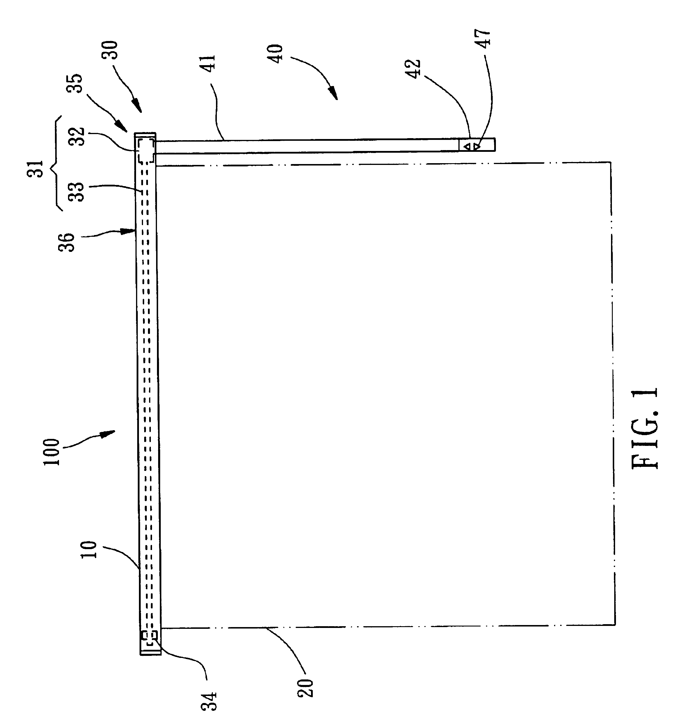
[0019]After detailed description of the structure and relative positioning of the parts of the present invention, the operation of the electricity-operated window blind 100 is outlined hereinafter.

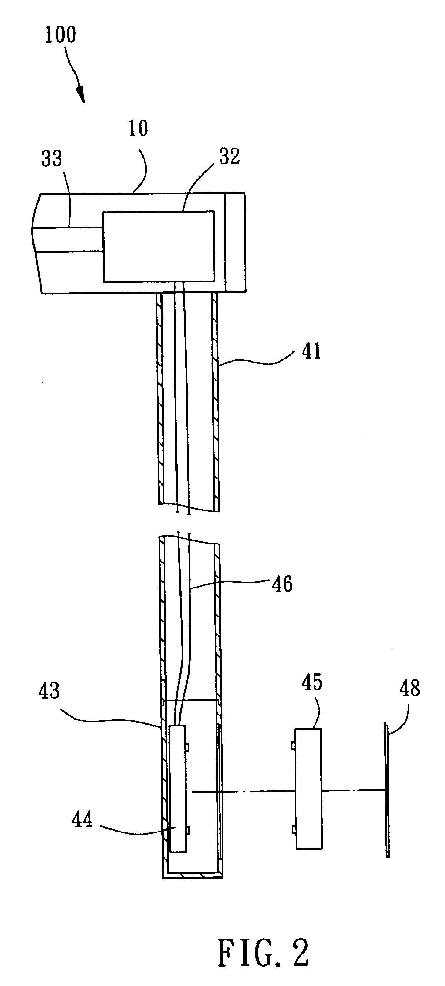
[0020]When wishing to change the shading status of the blind body 20, the user can directly operate the control switches 47 of the controller 42 to rotate the reversible motor 32 forwards or backwards, or to stop the reversible motor 32, thereby causing the shading status of the blind body 20 to be relatively changed. When the power of the battery set 45 of the controller 42 used up, the user can then open the battery lid 48 and then replace the battery set 45. After installation of a new battery set, the battery lid 48 is closed again.

[0021]Because the suspension rod 41 holds the controller 42 at an elevation accessible to the hand of a person, the user can conveniently operate the controller 42 to control the shading status of the blind body 20. When battery low, the user can convenientl...

second embodiment

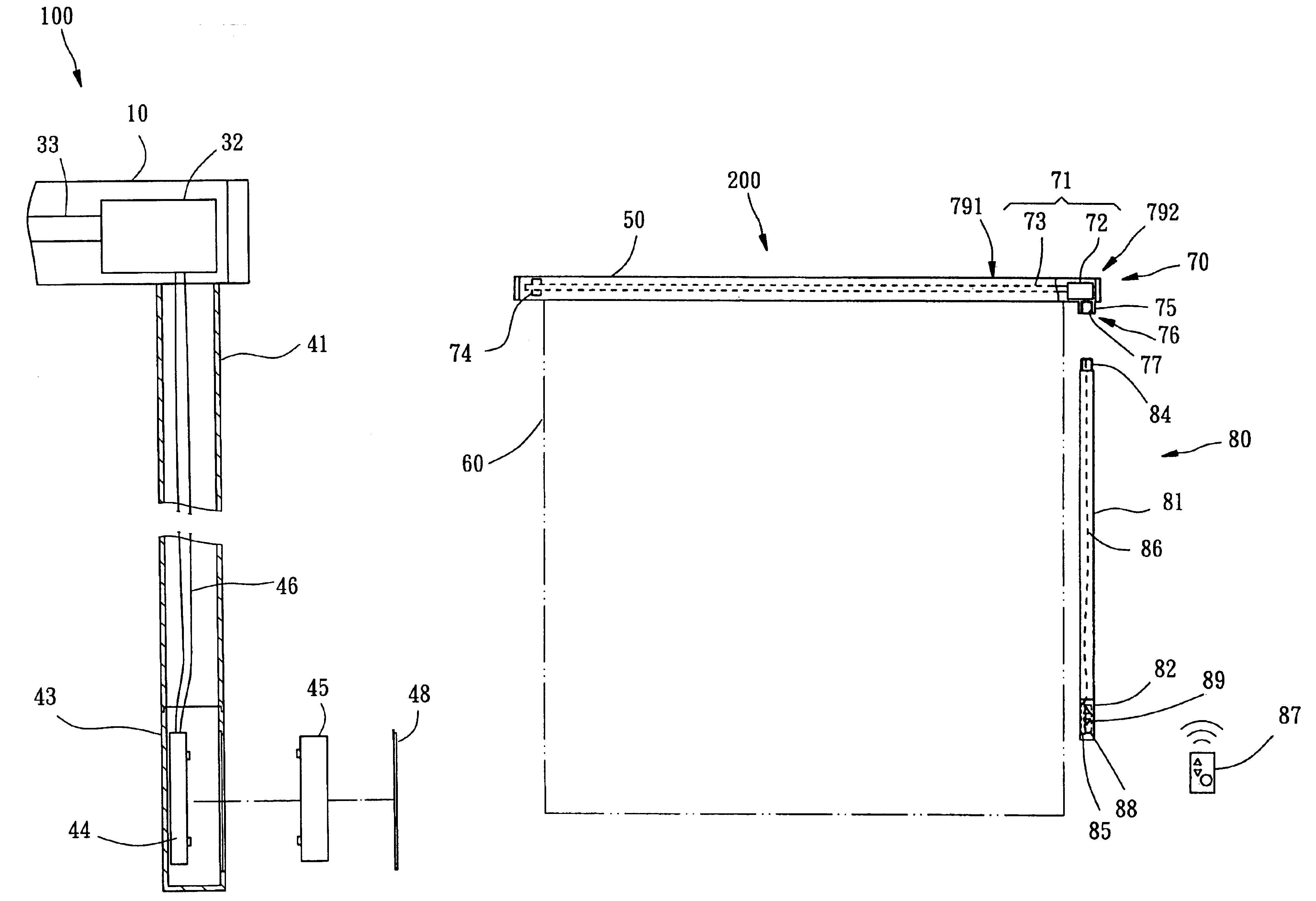
[0027]FIG. 5 shows an electricity-operated window blind 300 constructed according to the third preferred embodiment of the present invention. This embodiment is substantially similar to the aforesaid second embodiment of the present invention with exceptions outlined hereinafter.

[0028]The power input device 91 of the driving mechanism 90 is formed of a reversible motor 911 and a hexagonal rod member 912, which serve as the input device 91. The reversible motor 911 is mounted inside the headrail 10′. The hexagonal rod member 912 is installed in the headrail 10′, having a bottom side extended out of the headrail 10′ toward the operation position of the user and a coupling portion 92, for example, a V-groove 921 extended around the periphery near the bottom side, and a plurality of contacts 922 in the bottom edge of the bottom side.

[0029]The suspension rod 94 of the control mechanism 93 has a hexagonal coupling hole 941 in the top end, and retaining means 95 in the hexagonal coupling h...


PUM


Abstract

An electricity-operated window blind is constructed to include a headrail, a driving mechanism mounted inside the headrail and having a power input device for rotation upon receipt of power supply, and a power output device for synchronously rotating with the power input device, a bind body suspended below the headrail and coupled to the power output device and controlled by the power output device to change window shading status, and a control mechanism. The control mechanism includes a suspension rod downwardly suspended from the headrail by a first end thereof, and a controller installed in a second end of the suspension rod. The controller has a battery set electrically coupled to the power input device for providing the necessary working power to the power input device.

Description

BACKGROUND OF THE INVENTION[0001]1. Field of the Invention[0002]The present invention relates generally to a window blind and, more specifically, to an electricity-operated window blind, which enables the user to replace the battery set conveniently and safely.[0003]2. Description of the Related Art[0004]A conventional electric window blind is generally comprised of a headrail fixedly located on the top side of the window, a blind body (slat assembly or curtain) suspended below the headrail, a motor drive mounted inside the headrail and coupled to the blind body, and a battery set installed in the headrail to provide the necessary working power to the motor drive, for enabling the motor drive to roll up or let off the blind down and to further change the window shading status.[0005]Because the blind body is frequently opened and closed, the battery power of the battery set will be used up quickly. Further, due to limited space in the headrail, the sizes of the motor drive and the ba...

Claims


Application Information

Patent Timeline
Patent Type & Authority Patents(United States)
IPC IPC(8): E06B9/32E06B9/28E06B9/68
CPCE06B9/32
Inventor NIEN, MING
Owner NIEN MADE ENTERPRISE CO LTD
Learn More