Medical needle device with mis-punctuation prevention shield

a technology of needle shield and needle needle, which is applied in the field of medical needle shields, can solve the problems of difficult to weaken the force applied, contamination and infections caused by needlestick injuries with injection needles or puncture needles in medical facilities, and the injection needle comes off the punctured portion of the patien

Inactive Publication Date: 2004-12-09
JMS CO LTD
View PDF9 Cites 11 Cited by
  • Summary
  • Abstract
  • Description
  • Claims
  • Application Information

AI Technical Summary

Problems solved by technology

Conventionally, contamination and infections due to needlestick injuries with injection needles or puncture needles have been a problem in medical facilities.
This is because, even when the shield is fixed to the punctured portion of the patient for preventing the injection needle from leaving the retained state, if the injection needle is easily moved within the shield, there is the risk that the injection needle comes off the punctured portion of the patient.
Due to its configuration, however, it is difficult to weaken sufficiently the force applied when the injection needle is stored in the shield while ensuring the sufficiently large force for holding the injection needle with respect to the shield.
In the injection needle device described in U.S. Pat. No. 4,170,993, however, a configuration for holding the injection needle forms an obstacle, which makes it difficult for the injection needle to rotate with respect to the shield in the usage state in which the injection needle protrudes from the shield.
Also, in both of the configurations described in JP H6(1994)-7861B and JP H5(1993)-300942A, it is difficult to make the injection needle rotatable with respect to the shield in the usage state in which the injection needle protrudes from the shield.
Although the above problems are described referring to the example of the winged injection needle device, these problems arise commonly also in injection needle devices without wings.

Method used


Image

  • Medical needle device with mis-punctuation prevention shield
  • Medical needle device with mis-punctuation prevention shield
  • Medical needle device with mis-punctuation prevention shield

Examples


embodiment 1

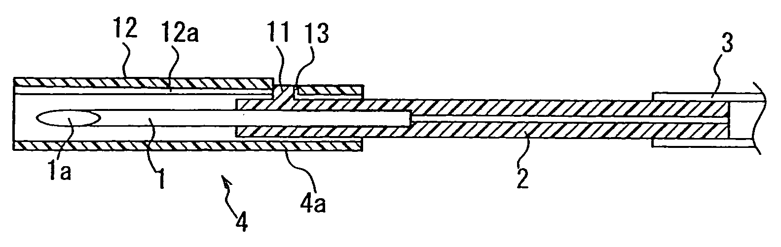
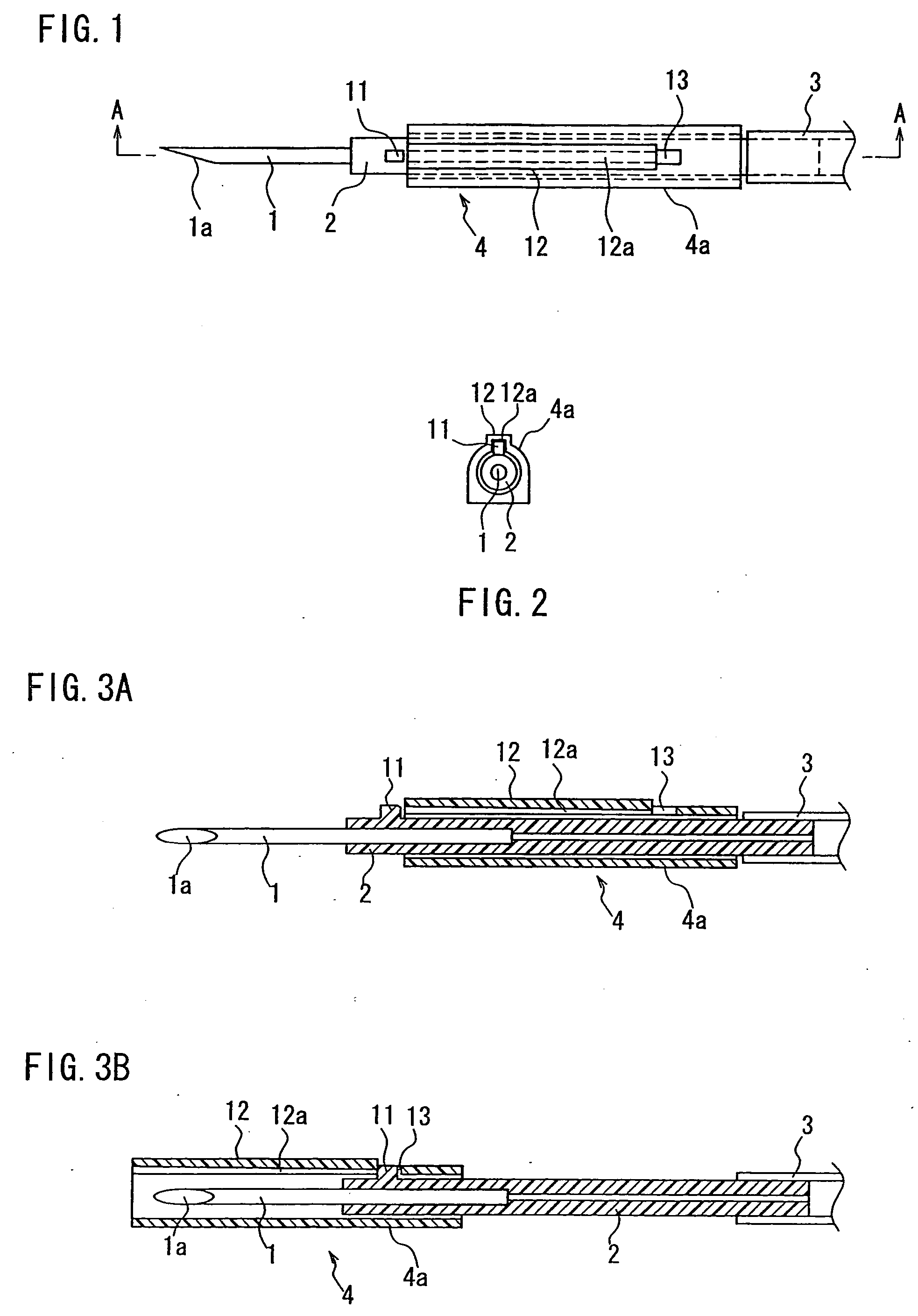
[0039] FIG. 1 is a plan view of a medical needle device of the present invention, and FIG. 2 is a side view of the medical needle device from a left side of FIG. 1. FIG. 3A is a cross-sectional view taken along the line A-A of FIG. 1. FIG. 3B is a cross-sectional view showing a state after a storing action is conducted on the device in the state of FIG. 3A.

[0040] Reference numeral 1 denotes a needle, which is fixed to a front end portion of a hub 2 made of resin. A tube 3 is connected to a rear end portion of the hub 2. Reference numeral 4 denotes a shield, including as a main body a shield tube 4a made of resin and having a substantially cylindrical shape. The hub 2 has a length such that a front end portion and a rear end portion thereof can protrude from the shield tube 4a when the hub 2 is inserted into an inner bore of the shield tube 4a. An outer diameter of the hub 2 has a size such that a slight gap can be formed between the hub 2 and an inner wall of the shield tube 4a so ...

embodiment 2

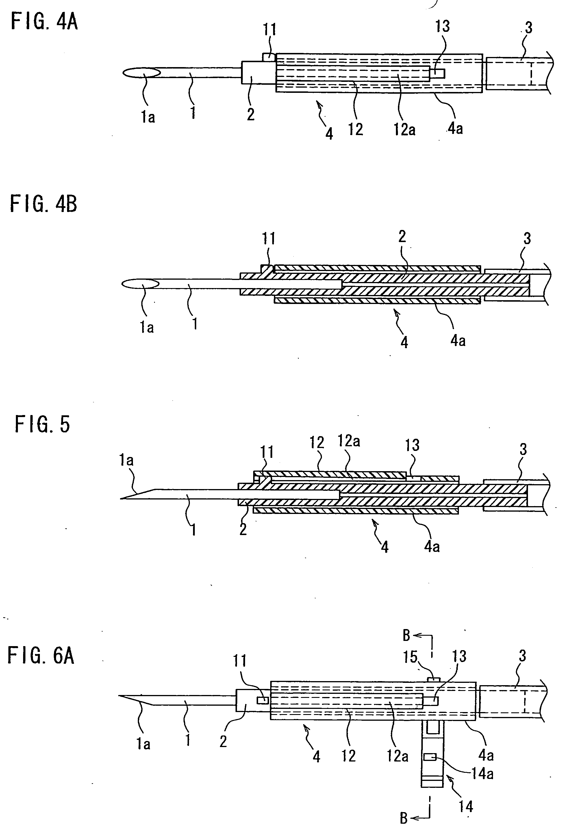
[0056] FIG. 8 is a plan view of a medical needle device according to Embodiment 2 of the present invention, and FIG. 9 is a side view of the medical needle device from a left side of FIG. 8. FIG. 10 is a cross-sectional view showing a planar shape of the same device. This embodiment relates to a configuration having a winged shield, in which left and right wings are given to the shield tube 4a of Embodiment 1 . The basic configurations of the shield tube and the hub are the same as in Embodiment 1 . Therefore, the elements that are the same as those in Embodiment 1 are given the same reference numerals for their explanations.

[0057] Reference numeral 1 denotes a needle, which is fixed to a front end portion of a hub 2 made of resin. A tube 3 is connected to a rear end portion of the hub 2. Reference numeral 24 denotes a winged shield, including a shield tube 24a made of resin and having a substantially cylindrical shape, and left and right wings 5 and 6. The hub 2 has a length such t...


PUM


Abstract

In a medical needle device having a shield for reduction of needlestick injuries, a protrusion is formed on an outer peripheral surface of a hub to which a needle is mounted, a height of the protrusion being set so that the protrusion protrudes beyond an inner diameter of a shield tube, and a gate groove is formed at an inner surface of the shield tube to extend from a front end to the vicinity of a rear end, dimensions of the gate groove being such that the protrusion can fit in a front end portion of the gate groove. In a state where the protrusion is exposed from the front end of the shield tube, the hub can rotate with respect to the shield tube. At a rotational position of the protrusion at which it does not face a front end of the gate groove, a position of the hub is limited so as not to move toward a rear end side of the shield tube due to engagement of the protrusion with a front end face of the shield tube. At a rotational position of the protrusion at which it face the front end of the gate groove, the protrusion can slide into the gate groove, whereby the hub can move so that a tip of the needle can be stored in the shield tube. In the penetrating state of the needle that enables the puncturing, the needle cannot move in the shield for reduction of needlestick injuries and can rotate.

Description

[0001] 1. Field of the Invention[0002] The present invention relates to medical needle devices, and more particularly relates to medical needle devices having a shield for the reduction of needlestick injuries, in which a used needle can be stored safely.[0003] 2. Related Background Art[0004] Conventionally, contamination and infections due to needlestick injuries with injection needles or puncture needles have been a problem in medical facilities. In particular, recently, as hepatitis B, hepatitis C, HIV (human immunodeficiency virus) and the like have received widespread attention, there is a strong demand for means that actively reduce such needlestick injuries.[0005] As a means for preventing such needlestick injuries, a configuration in which a cylindrical shield is provided so that the shield can slide with respect to the injection needle is known. That is, depending on the sliding position of the shield, the injection needle is either exposed or it is contained in the shield....

Claims


Application Information

Patent Timeline
Patent Type & Authority Applications(United States)
IPC IPC(8): A61M5/32A61M5/158
CPCA61M5/3271A61M5/158
Inventor HONGO, SUSUMUKIYONO, TAKAFUMIMORIWAKI, KUNIHARU
Owner JMS CO LTD
Why Eureka
Try Eureka