

Assembling method and device for stator and rotor of generator
A technology for stators and rotors and generators, which is applied in the manufacture of stators/rotor bodies, etc., can solve the problems that the speed of action cannot be completely consistent, the stator and rotor are difficult to fit, and the surface of the stator is bumped. And the effect of convenient transportation
- Summary
- Abstract
- Description
- Claims
- Application Information
AI Technical Summary
Problems solved by technology
Method used
Image

Examples
Embodiment Construction
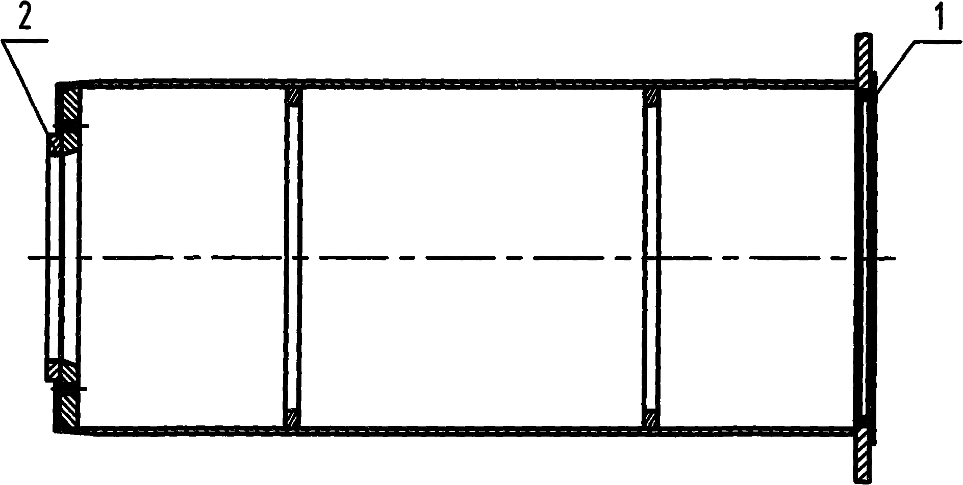
[0010] refer to figure 1 , The guide shaft is a cylindrical structure, one end of the guide shaft cooperates with the assembly surface of the large bearing of the stator main shaft and is supported on the end surface of the inner ring of the large bearing, and the other end of the guide shaft cooperates with the assembly surface of the small bearing of the stator main shaft. In order to avoid deformation of the guide shaft, 2 to 3 ribs are welded inside. In order to prevent the guide shaft from scratching the bearing assembly surface of the stator main shaft, the guard plate 1 and the guard plate 2 are fixed on the mating surface of the guide shaft and the stator main shaft. 12) Brass plates or bonded PTFE plates about 4-5mm thick and 40-60mm wide. In order to make the sliding sleeve enter the guide shaft smoothly, the end where the sliding sleeve enters on the guide shaft is made into a tapered structure of 80-100 mm.
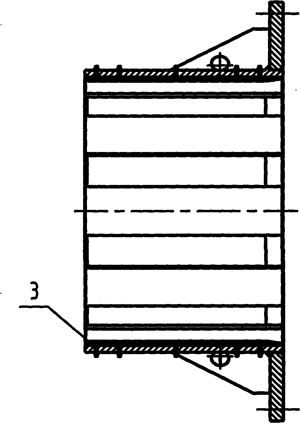
[0011] refer to figure 2 , the sliding sleeve is a c...
PUM
 Abstract
Description
Claims
Application Information