Airflow guiding structure for a heat-dissipating fan

a technology of airflow and heat dissipation fan, which is applied in the direction of machines/engines, liquid fuel engines, electric apparatus casings/cabinets/drawers, etc., can solve the problems of poor heat dissipation effect, adverse heat dissipation effect, and non-uniform heat dissipation, so as to improve the overall heat dissipation efficiency, reduce wind noise, and increase wind pressure

Inactive Publication Date: 2005-06-28
SUNONWEALTH ELECTRIC MACHINE IND
View PDF5 Cites 35 Cited by
  • Summary
  • Abstract
  • Description
  • Claims
  • Application Information

AI Technical Summary

Benefits of technology

[0006]An object of the present invention is to provide an air-guiding structure for a heat-dissipating fan that includes at least one guiding ring in an air outlet of the heat-dissipating fan for concentrating and guiding airflow, increasing wind pressure, reducing wind noise, and improving the overall heat-dissipating efficiency.
[0007]Another object of the present invention is to provide an air-guiding structure for a heat-dissipating fan that includes at least one guiding ring in an air outlet of the heat-dissipating fan. The guiding ring extends radially inward or outward relative to a longitudinal direction of the casing, thereby concentrating and guiding airflow, increasing wind pressure, reducing wind noise, and improving the overall heat-dissipating efficiency.
[0008]A further object of the present invention is to provide an air-guiding structure for a heat-dissipating fan that includes at least one guiding ring in an air outlet of the heat-dissipating fan. An inclination angle of the guiding ring is selected to guide airflow to a desired area for concentrated heat dissipation or for enlarging the heat-dissipating area, thereby improving the overall heat-dissipating efficiency and making the assembly and design of the heat-dissipating fan more flexible.SUMMARY OF THE INVENTION

Problems solved by technology

In a case that the object is not located directly below the air outlet 12, the airflow cannot flow through the object in a uniform manner, resulting in non-uniform heat dissipation and poor heat-dissipating effect.
On the other hand, since the object is generally mounted in a limited space such as in a notebook type computer (or a laptop computer) in a position not directly below the base 13 or outside the area of air outlet, the heat-dissipating effect is adversely affected.
The heat-dissipating effect is also adversely affected if the object is too large to be completely within an area directly below the heat-dissipating fan.
Further, turbulence tends to occur when the airflow is passing through the ribs 14.

Method used


Image

  • Airflow guiding structure for a heat-dissipating fan
  • Airflow guiding structure for a heat-dissipating fan
  • Airflow guiding structure for a heat-dissipating fan

Examples


first embodiment

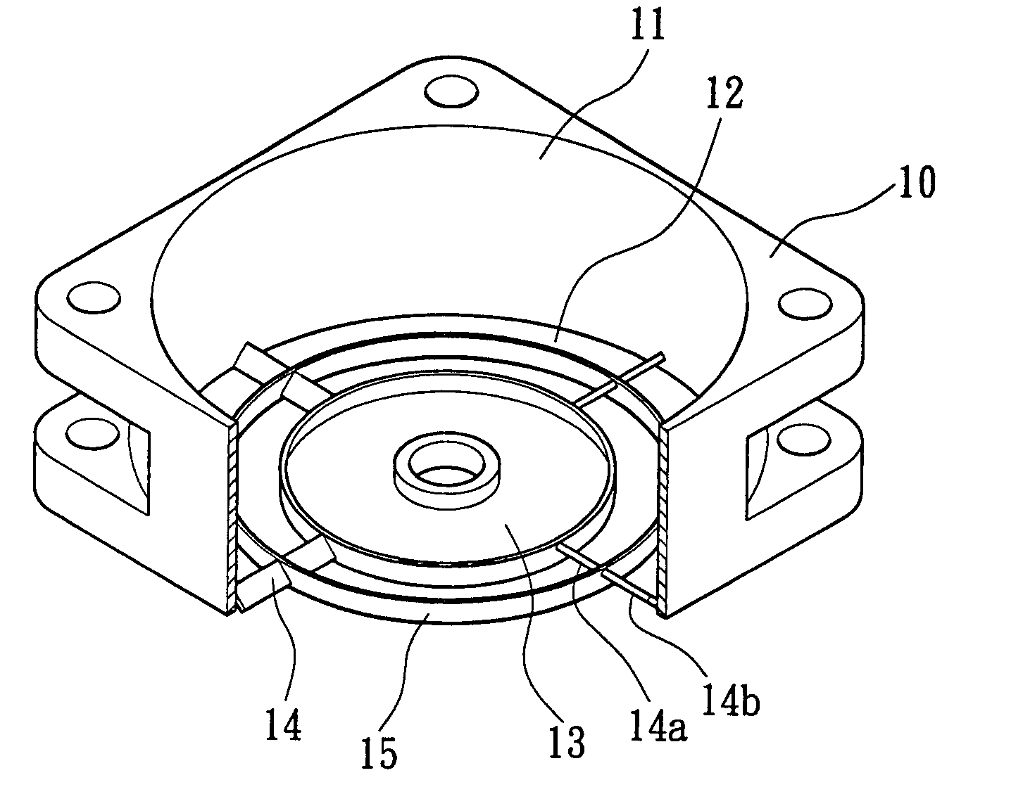
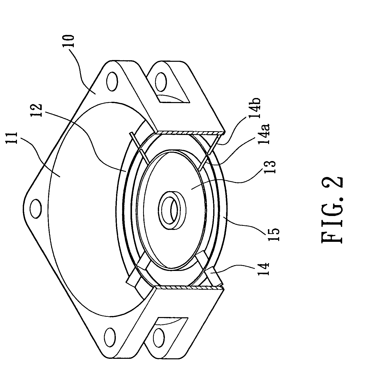
[0034]Referring to FIGS. 2, 3, 4, and 4A, a heat-dissipating fan with an air guiding structure in accordance with the present invention includes a casing 10, an air inlet 11, an air outlet 12, a base 13, a plurality of ribs 14, and a guiding ring 15. The casing 10 may be made of plastics or metal, with the air inlet 11 and the air outlet 12 being respectively defined in two opposite sides of the casing 10. The base 13 is located in the air outlet 12, and an impeller 20 (FIG. 4) is mounted on the base 13. The ribs 14 extend between the base 13 and the casing 10 along a radial direction of the base 13. The guiding ring 15 is located between the base 13 and the casing 10 (FIG. 4) and extends along a longitudinal direction of the casing 10. Further, the guiding ring 15 extends across the ribs 14 and is fixedly mounted to the ribs 14. As illustrated in FIG. 4A, the guiding ring 15 has an axial length L that is preferably longer than a width W of the guiding ring 15 in the radial directio...

second embodiment

[0037]FIGS. 5 through 7 illustrate a heat-dissipating fan with the air guiding structure in accordance with the present invention. In this embodiment, the guiding ring 15 extends downwardly (downstream) and radially outward away from the base 13, best shown in FIG. 7.

[0038]Still referring to FIG. 7, when the impeller turns 20, the blades 21 of the impeller 20 introduce airflow into the casing 10 via the air inlet 11 and expel the airflow via the air outlet 12, thereby dissipating heat from an object such as a fin or central processing unit (not shown). When the airflow passes through the guiding ring 15 and the ribs 14, the guiding ring 15 that extends downwardly and radially outward divides the airflow into an inner portion 17 that is guided downward and an outer portion 16 that is guided downward and outward to an area outside the air outlet 12. Thus, more area can be cooled by the heat-dissipating fan. Also, the heat-dissipating fan is suitable for use in a limited space (e.g., i...

third embodiment

[0041]FIG. 8 illustrates a heat-dissipating fan with the air guiding structure in accordance with the present invention. In this embodiment, the guiding ring 15 extends downward (downstream) and radially inward. Thus, an inner portion 17 of airflow is guided toward an object directly below the base 12, providing improved heat-dissipating efficiency. Following the inclining direction of the guiding ring 15, the wind pressure is increased by the guiding ring 15. Further, since the wind pressure of the inner portion 17 of the airflow exiting the air outlet 12 is increased due to downward and radially inward inclination of the guiding ring 15, the outer portion 16 of the airflow tends to flow radially inward, providing a concentration effect for the airflow for dissipating heat.


PUM


Abstract

A heat-dissipating fan includes a casing having an air outlet, a base mounted in the air outlet, an impeller being mounted on the base and having a plurality of blades, a plurality of ribs each extending between the base and the casing along a radial direction of the base, and at least one guiding ring fixedly mounted to the ribs. The guiding ring has an axial length that is longer than a width of the guiding ring in the radial direction. The guiding ring guides and divides airflow passing through the air outlet when the impeller is turning.

Description

BACKGROUND OF THE INVENTION[0001]1. Field of the Invention[0002]The present invention relates to an airflow guiding structure for a heat-dissipating fan.[0003]2. Description of Related Art[0004]FIG. 1 of the drawings illustrates a typical heat-dissipating fan including a casing 10, an air inlet 11 defined in a side of the casing 10, an air outlet 12 defined in the other side of the casing 10, a base 13, and a plurality of ribs 14. The base 13 is secured by the ribs 14 in the air outlet 12. A stator (not shown) and an impeller (not shown) are mounted to the base 13. When the impeller turns, air is sucked into the casing 10 via the air inlet 11 and exits the casing 10 via the air outlet 12 to dissipate heat from an object such as a fin or a central processing unit.[0005]Although the above-mentioned heat-dissipating fan provides a certain heat-dissipating effect, the heat-dissipating operation can only be performed on an object directly below the air outlet 12, as the airflow can only ...

Claims


Application Information

Patent Timeline
Patent Type & Authority Patents(United States)
IPC IPC(8): F03B1/00F04D29/40F04D29/54H05K5/00F04D29/66
CPCF04D29/667F04D29/542F04D29/544
Inventor HORNG, ALEXHONG, YIN-RONGHONG, CHING-SHENG
Owner SUNONWEALTH ELECTRIC MACHINE IND
Why Eureka
Try Eureka