Communication network and protocol which can efficiently maintain transmission across a disrupted network

Inactive Publication Date: 2005-06-28
RPX CORP
View PDF8 Cites 54 Cited by
  • Summary
  • Abstract
  • Description
  • Claims
  • Application Information

AI Technical Summary

Benefits of technology

[0013]In ring and mesh topologies, a transmission path between any two modules preferably contains at least two transmission channels. A single transmission path extends around a ring topology, and one or more paths extend between modules of a star or mesh topology. If the entire transmission path is disturbed between a pair of modules coupled in the ring topology, communication to either of those modules can be maintained provided transmission is sent in the proper direction around the ring. The location at which the transmission path is disturbed can be arrived at by the last module adjacent the disturbance not detecting a null bit pattern for a period of time exceeding that need to transfer a packet. As noted herein, disturbances cause errors in transmission across the network. There are various types of disturbances. For example, disturbances may include not only severance of a channel, but also practices such as a network system administrator setting a node inactive or other error detection and reporting methodologies. Responsive to error/disturbance detection, the receiving module will return the packet through a loop-back conductor of that module to the originating module. The returned packet preferably includes control bits and error identification bits in the header and trailer portions of the packet. The control bits indicate that an error exists (i.e., that the tr

Problems solved by technology

As noted herein, disturbances cause errors in transmission across the network.
For example, disturbances may include not only severance of a ch

Method used


Image

  • Communication network and protocol which can efficiently maintain transmission across a disrupted network
  • Communication network and protocol which can efficiently maintain transmission across a disrupted network
  • Communication network and protocol which can efficiently maintain transmission across a disrupted network

Examples


Embodiment Construction

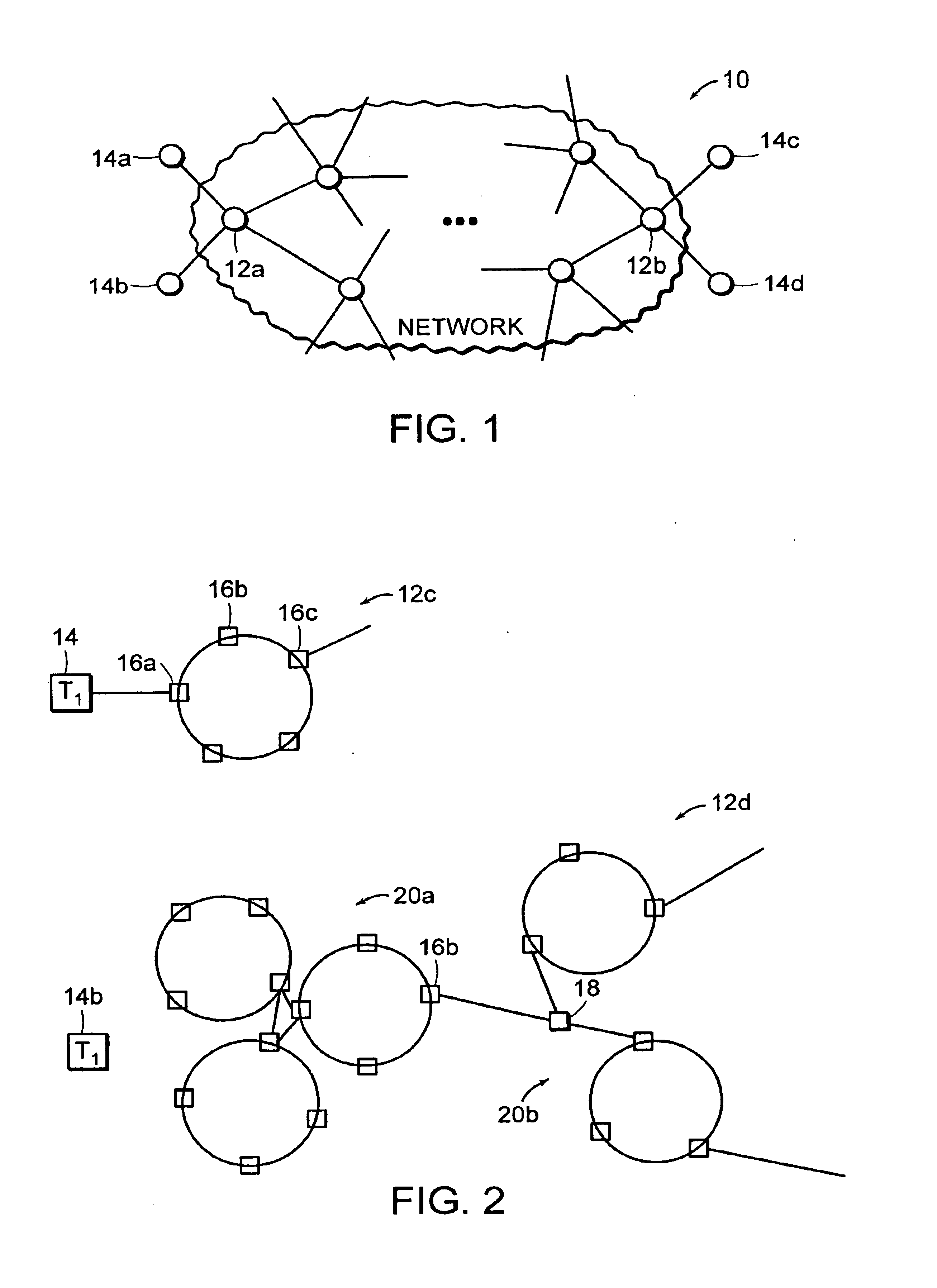
[0026]Turning now to the drawings, FIG. 1 illustrates a communication network 10. Network 10 includes an interconnection of subnets linked by nodes 12. Network 10 can be thought of as one or more intranets interconnected with one another, or interconnected via an internet.

[0027]Each node 12 may embody a subnet or a plurality of interconnected subnets. Select nodes 12a and 12b can be used to receive input data into the structured network or transmit output data from the structured network. Nodes 12a and 12b can be connected to external nodes of a conventional network or to termination devices 14.

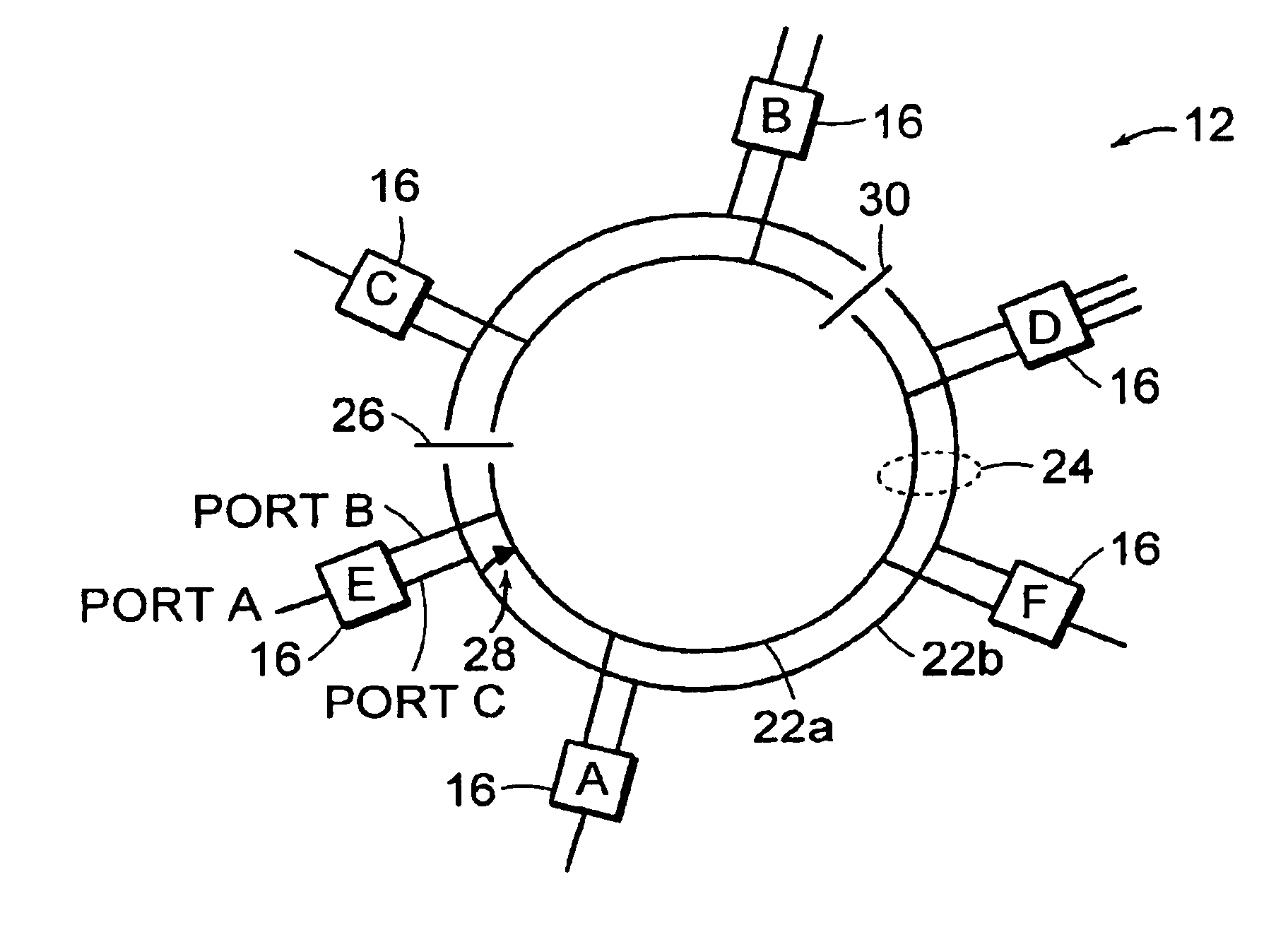
[0028]FIG. 2 illustrates exemplary forms of node 12 and, more specifically, modules 16. In the example shown, an entry module 16a receives packets of data from a termination device 14. Node 12c illustrates a node comprising modules interconnected about a ring topography, referred to as a “loop”. Along with the entry module16a are intermediate modules 16b and 16c.

[0029]It is recognized that a...


PUM


Abstract

A packet architecture, communication system, and method are provided for determining the location at which a network is disrupted, disabled, and/or severed. The packet can contain control bits and error identification bits which note the location at which disturbance exists, and informs the originating module to take alternative path if necessary. The alternative path can be applied to either re-sending the existing packet or sending future packets between certain modules connected to the network, wherein the network preferably includes one or more ring topologies interconnected with one another between termination devices. The termination devices allow communication across subnets which form an intranet or across a global system, or internet. Although redundant transmission channels are used, each transmission channel preferably does not send redundant packets, nor are the transmission channels dedicated as uni-directional. Instead, each of the redundant transmission channels can send dissimilar packets in a bi-directional fashion.

Description

BACKGROUND OF THE INVENTION[0001]1. Field of the Invention[0002]This invention relates to a communication system (“network”) that accommodates wrapped packets, each of which includes error control bits that, in conjunction with unique identifiers assigned to each module or switch connected to the network, detect the location at which the network is severed and yet maintains efficient transfers across the network.[0003]2. Description of the Related Art[0004]A communication network is generally regarded as an interconnected set of subnetworks or subnets. The network can extend over localized subnets as an intranet or can extend globally as an internet between one or more intranets. A communication network can therefore forward data within a localized network between termination devices extending to almost anywhere around the world. The termination devices include any data entry / retrieval system (e.g., telephone or computer), and a network includes a local and / or global interconnection...

Claims


Application Information

Patent Timeline
IPC IPC(8): H04L12/437
CPCH04L12/437H04L2012/421
Inventor MAHALINGAIAH, RUPAKA
Owner RPX CORP
Why Eureka
Try Eureka