Optimized fiber optic cable suitable for microduct blown installation

a fiber optic cable and microduct technology, applied in the direction of optics, fibre mechanical structures, instruments, etc., can solve the problems of inability to manufacture loose tubes, large force to be applied to cables, and failure of standard ducts and conventional fiber optic cables to maximize the volume available in ducts

Inactive Publication Date: 2005-06-28
ALCATEL LUCENT SAS
View PDF15 Cites 205 Cited by
  • Summary
  • Abstract
  • Description
  • Claims
  • Application Information

AI Technical Summary

Problems solved by technology

This installation procedure caused a significant amount of force to be applied on the cable due to friction inherent in a pulling installation.
Further, the use of standard ducts and conventional fiber optic cables failed to maximize the volume available in the duct.
It has heretofore been impossible to manufacture a loose tube (i.e., wherein fibers are loose within the buffer tubes) cable small enough to be effectively used within microducts, while still achieving a high fiber density.
However, such central tube type designs suffer many disadvantages.
Although the radial strength members provide good axial reinforcement for the optical cable, they also greatly inhibit the ability of the cable to bend during installation.
These characteristics degrade the ability of such cables to be used in blown installations.
Further, the conventional jacket material, along with the jacket's smooth outer surface, impedes the ability to use blown installation, because of the high friction and large surface area contact between the jacket's outer surface and the inner surface of the microduct, and the lack of friction between the smooth jacket and air or other fluid passing over the cable.
Lastly, the requirement of axially placed strength members degrades the amount of area available for optical units, and therefore has a corresponding decrease in the cable's optical performance.

Method used


Image

  • Optimized fiber optic cable suitable for microduct blown installation
  • Optimized fiber optic cable suitable for microduct blown installation
  • Optimized fiber optic cable suitable for microduct blown installation

Examples


Embodiment Construction

[0028]While the invention is open to various modifications and alternative forms, specific embodiments thereof are shown by way of examples in the drawings and are described herein in detail. There is no intent to limit the invention to the particular forms disclosed.

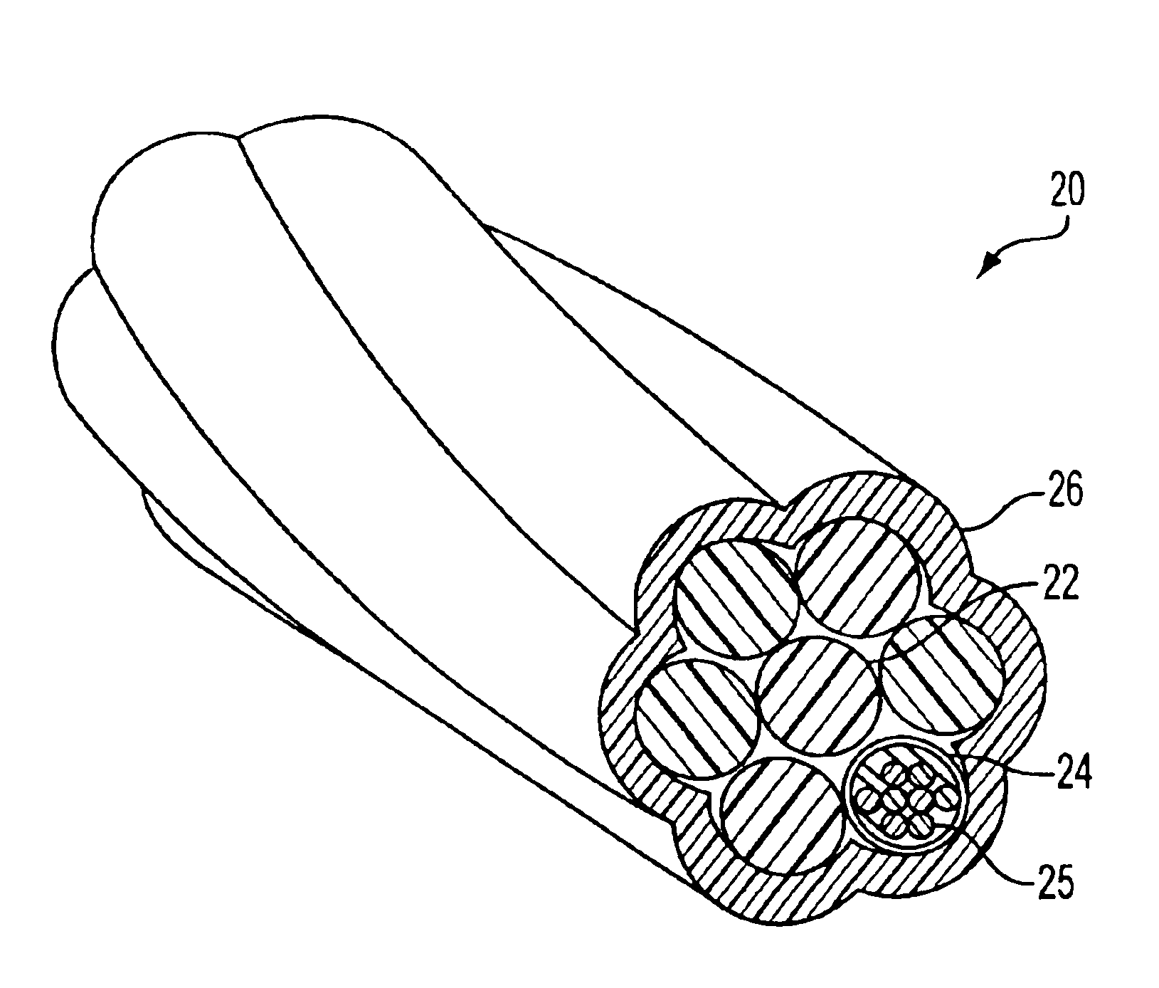
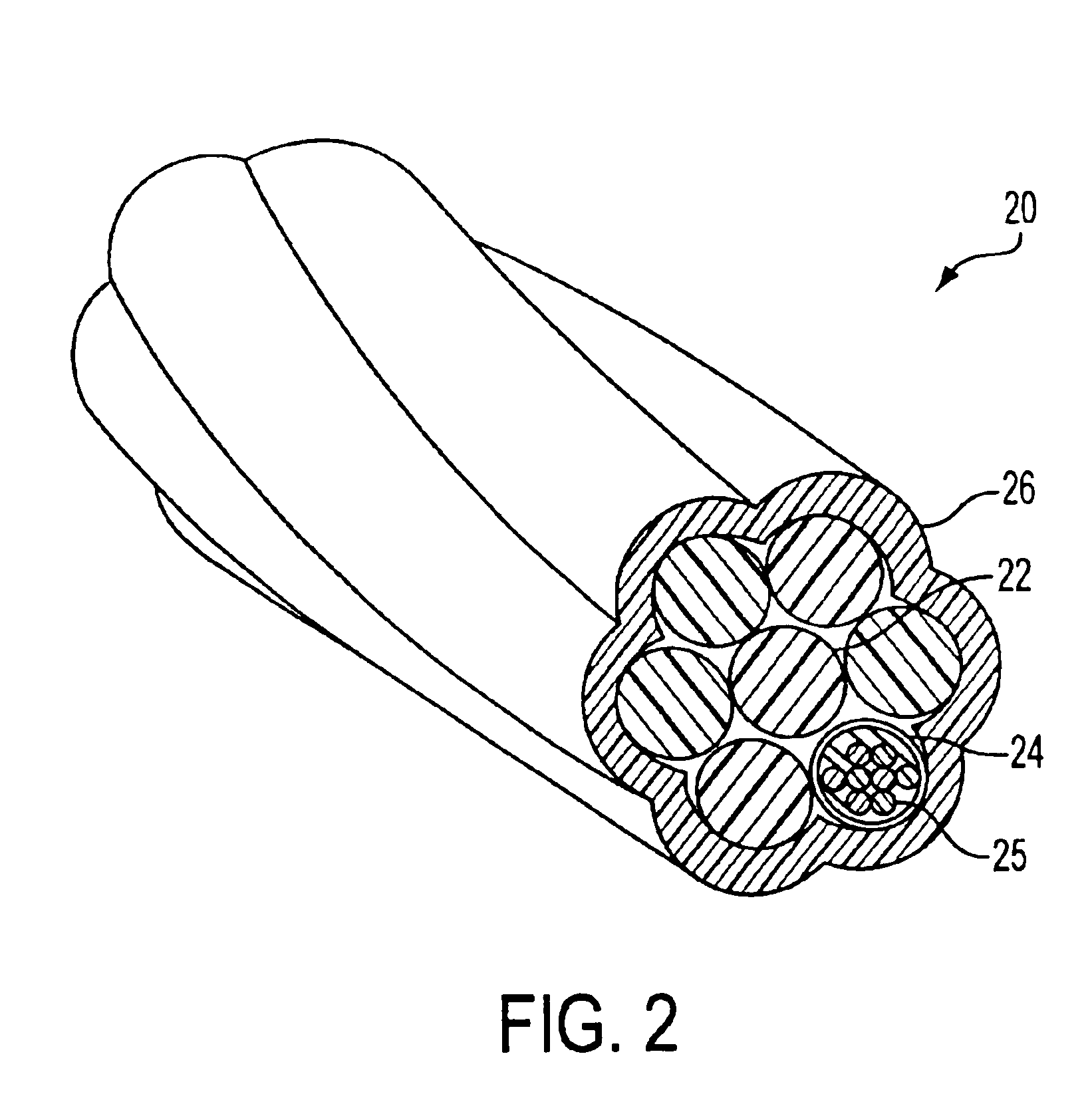
[0029]In one embodiment, the proposed cable design provides improved usability, due to the provision of a central strength member, which minimizes bending stiffness and has no preferential bending plane, yet provides sufficient axial stiffness to prevent the cable from buckling during installation. Axial stiffness minimizes cable expansion and contraction during temperature extremes.

[0030]The proposed cable design also helps to provide increased blowing performance. For example, the cable may include a low coefficient of friction jacket material, which decreases the friction between the cable and the duct, thereby increasing the blowing performance.

[0031]Further, the cable may include a textured outer surface to help in...


PUM


Abstract

A fiber optic cable with optical fibers stranded around a central strength member, and surrounded outer jacket made of a low coefficient of friction material and thinly constructed to show the profile of the stranded shape of the optical lines through the jacket, to thereby form a textured surface.

Description

[0001]This application claims the benefit of U.S. Provisional Application 60 / 426,395 filed Nov. 15, 2002, the disclosure of which is incorporated herein by reference.TECHNICAL FIELD[0002]This invention generally relates to electrical or other communication signal carriers, such as optical cables. More specifically, this invention relates to an optimized stranded optical cable design with a textured outer surface and low friction jacket material suitable for installation into micro-ducts via blown installation.BACKGROUND[0003]Conventionally, fiber optic cables (˜15 mm O.D.) were installed in standard underground ducts (1.25 in / 32 mm I.D.) by pulling cables through the ducts. This installation procedure caused a significant amount of force to be applied on the cable due to friction inherent in a pulling installation. Thus, a new method for installing fiber optic cables was developed that utilized compressed air blown into the duct to install the cable (i.e., “blown installation”). Thi...

Claims


Application Information

Patent Timeline
Patent Type & Authority Patents(United States)
IPC IPC(8): G02B6/44
CPCG02B6/4438
Inventor ROSSI, MICHAEL T.STORAASLI, OLAFLAUSCH, PETERBOURGET, VINCENTKELLY, AARONDALLAS, GEORGE
Owner ALCATEL LUCENT SAS
Why Eureka
Try Eureka