Methods and systems for implementing shared disk array management functions

a technology of shared disk arrays and management functions, applied in the direction of program control, fault response, instruments, etc., can solve the problems of inaccessible information maintained in the raid system managed by the failed controller, inefficient solution, and system performance bottlenecks, and achieve high-scalability disk arrays

Inactive Publication Date: 2005-06-28
EMC IP HLDG CO LLC
View PDF17 Cites 68 Cited by
  • Summary
  • Abstract
  • Description
  • Claims
  • Application Information

AI Technical Summary

Benefits of technology

[0079]One advantage of the shared redundancy group management (SRGM) techniques of the present invention is that SRGM allows for distributing reconstruction processing to all AMFs sharing a RG. This results in faster reconstruction times and a general reduction in the increased response times normally encountered by a host during reconstruction. Distributed reconstruction is accomplished by having a subset (or all) of the AMFs sharing a RG coordinate for which stripes each will be responsible for reconstructing. If any of these AMFs fail or shutdown during reconstruction, the remaining AMFs re-arbitrate reconstruction responsibilities. For example, suppose there are N AMFs sharing a redundancy group that needs reconstruction. These AMFs talk to each other (by sending messages) and determine which ones are to participate in the reconstruction, e.g., a subset of N, denote by M. These M AMFs determine reconstruction responsibilities by determining which AMFs will reconstruct which stripe(s). This can be determined by any algorithm. In one embodiment of the invention, for example, each AMFi reconstructs stripe(s) Mod(S / i), where S is the stripe number.

Problems solved by technology

This can lead to bottlenecks in system performance as the storage managed by a particular RAID controller can only be accessed through that RAID controller.
Furthermore, if a controller fails, information maintained in the RAID system managed by the failed controller becomes inaccessible.
This solution is very inefficient, however, as the slave controller is not used until a failure in the master has occurred.
However, this solution also has some performance drawbacks.
For example, the performance in such a master / slave architecture is bound by the speed of the master controller such that performance is not scalable.

Method used


Image

  • Methods and systems for implementing shared disk array management functions
  • Methods and systems for implementing shared disk array management functions
  • Methods and systems for implementing shared disk array management functions

Examples


Embodiment Construction

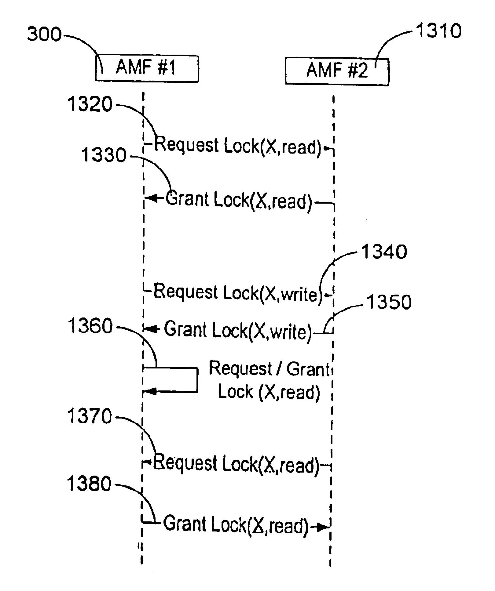
[0039]The present invention provides for shared redundancy group management (SRGM) between multiple AMFs so that multiple AMFs can simultaneously access the same redundancy group. According to the present invention, distributed synchronization and replication techniques are used to coordinate the activities of all AMFs sharing a redundancy group and to maintain data reliability. Access to any redundancy group can be gained through any controller that includes an AMF that is sharing control of that redundancy group. The AMFs sharing a resource group are therefore peers. Additionally, if a redundancy group is configured for shared access and a controller fails, access to data through the failed controller is blocked, but the data on the redundancy group is still intact, protected from disk failures, and accessible from any other controller that includes an AMF which is sharing that redundancy group. Within a given controller, multiple AMFs may be present, in which case redundancy grou...


PUM


Abstract

Multiple Array Management Functions (AMFs) are connected to multiple redundancy groups over a storage area network (SAN), such as a fiber-channel based SAN. The multiple AMFs share management responsibility of the redundancy groups, each of which typically includes multiple resources spread over multiple disks. The AMFs provide concurrent access to the redundancy groups for associated host systems. When a host requests an AMF to perform an operation on a resource, the AMF synchronizes with the other AMFs sharing control of the redundancy group that includes the resource to be operated on, so as to obtain a lock on the resource. While performing the operation, the AMF send replication data and state information associated with the resource such that if the AMF fails, any of the other AMFs are able to complete the operation and maintain data reliability and coherency.

Description

CROSS REFERENCE TO RELATED APPLICATIONS[0001]This application is a continuation of U.S. patent application Ser. No. 09 / 261,906 filed Mar. 3, 1999, now U.S. Pat. No. 6,148,414 and claims the benefit of U.S. Provisional Patent Application No. 60 / 101,742 filed Sep. 24, 1998, the disclosures of which are incorporated herein by reference.BACKGROUND OF THE INVENTION[0002]The present invention relates in general to systems and methods for eliminating bottlenecks in data storage networks, and in direct server attached storage, and more specifically to systems and methods for implementing dynamically shared redundancy group management between multiple disk array management functions.[0003]The need for faster communication among computers and data storage systems requires ever faster and more efficient storage networks. In recent years, implementation of clustering techniques and storage area networks (SANs) have greatly improved storage network performance. In a typical storage network, for ...

Claims


Application Information

Patent Timeline
Patent Type & Authority Patents(United States)
IPC IPC(8): G06F11/00H04L1/22G06F3/06G06F11/20H04L29/08
CPCG06F3/0607H04L67/1097G06F3/0613G06F3/0614G06F3/0619G06F3/0632G06F3/065G06F3/067G06F3/0689G06F9/526G06F11/1088G06F11/1096G06F11/2089G06F11/2097G06F3/061G06F11/2094G06F2201/85
Inventor BROWN, WILLIAM P.MATHEWS, MICHAEL B.
Owner EMC IP HLDG CO LLC
Why Eureka
Try Eureka