Polyvalent test stand

Inactive Publication Date: 2005-07-05
INNOVATIONS INDS JOUBERT
View PDF8 Cites 15 Cited by
  • Summary
  • Abstract
  • Description
  • Claims
  • Application Information

AI Technical Summary

Benefits of technology

[0013]An object of the present invention is ther

Problems solved by technology

However, these apparatuses often become damaged, either through normal use or through abuse by their users.
In this case, it often happens that the apparatus becomes unsafe and becomes unable to lift a load for which it is normally rated.
By their nature, the loads manipulated by lifting apparatuses are relatively heavy and can cause a lot of damages and injuries if, for any reason, the apparatus breaks and frees the load.
However, since testing requires that the apparatus be removed from its operation site while being tested, users of such apparatuses typically only perform preventive testing at the minimum frequency required by law.
In addition, the removal of the apparatu

Method used


Image

  • Polyvalent test stand
  • Polyvalent test stand
  • Polyvalent test stand

Examples


Embodiment Construction

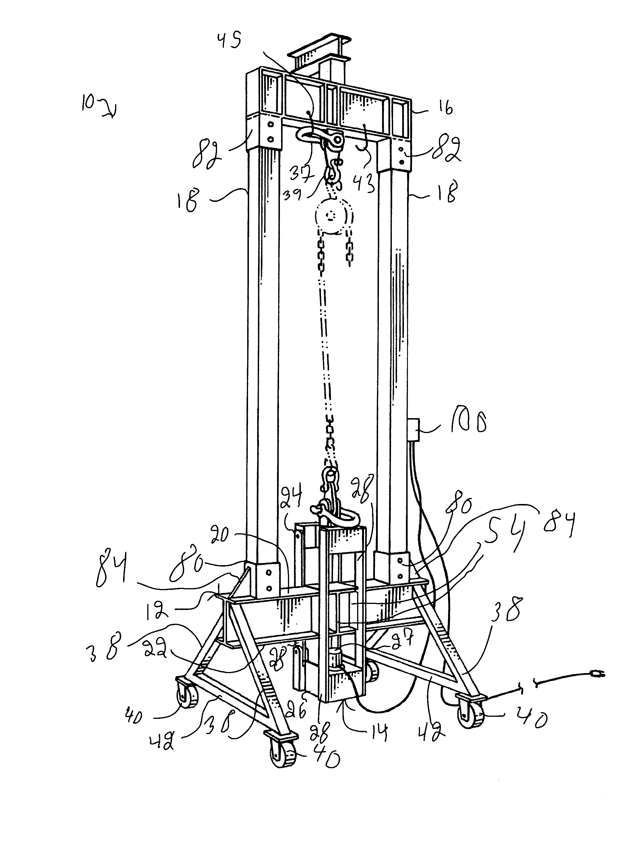
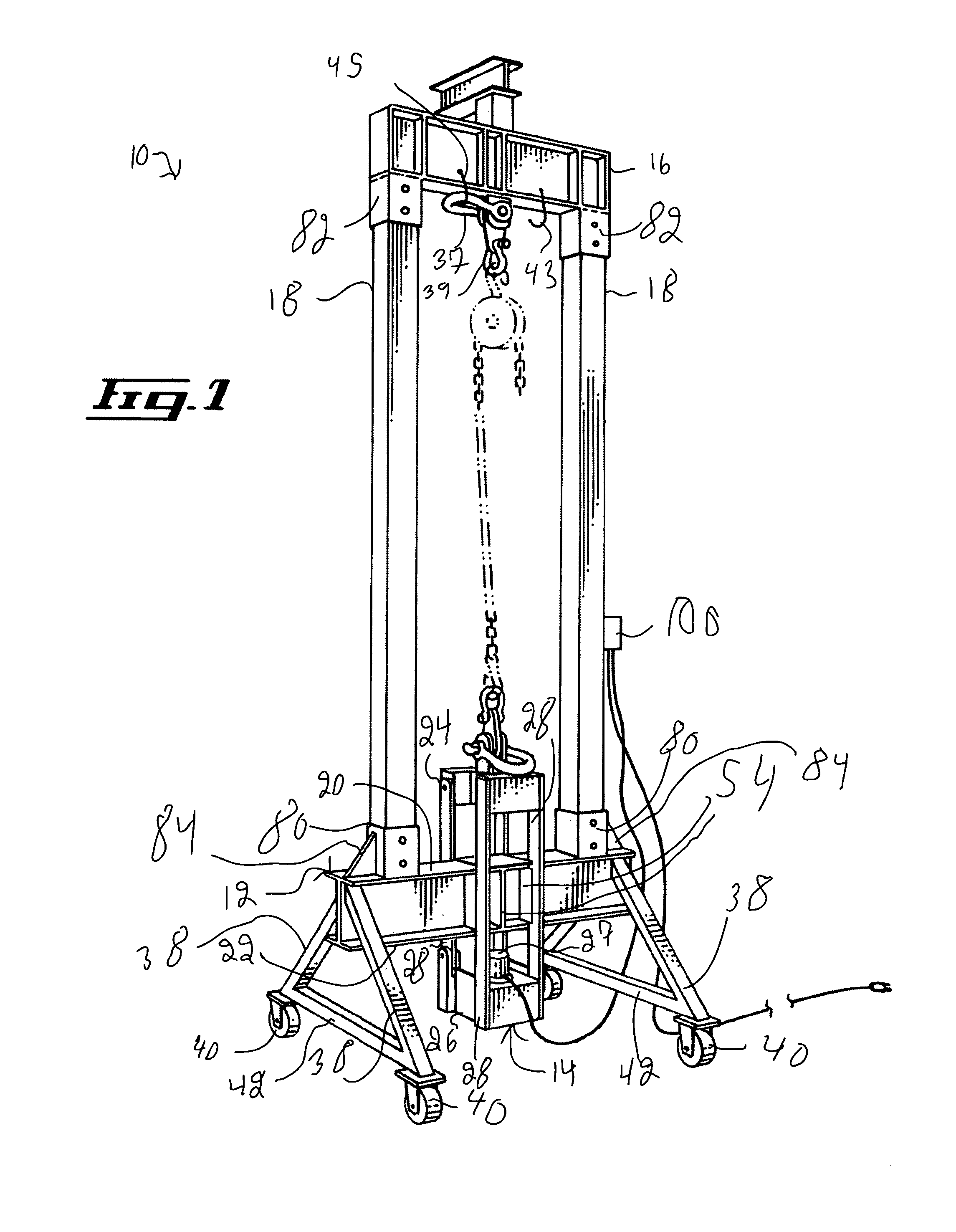
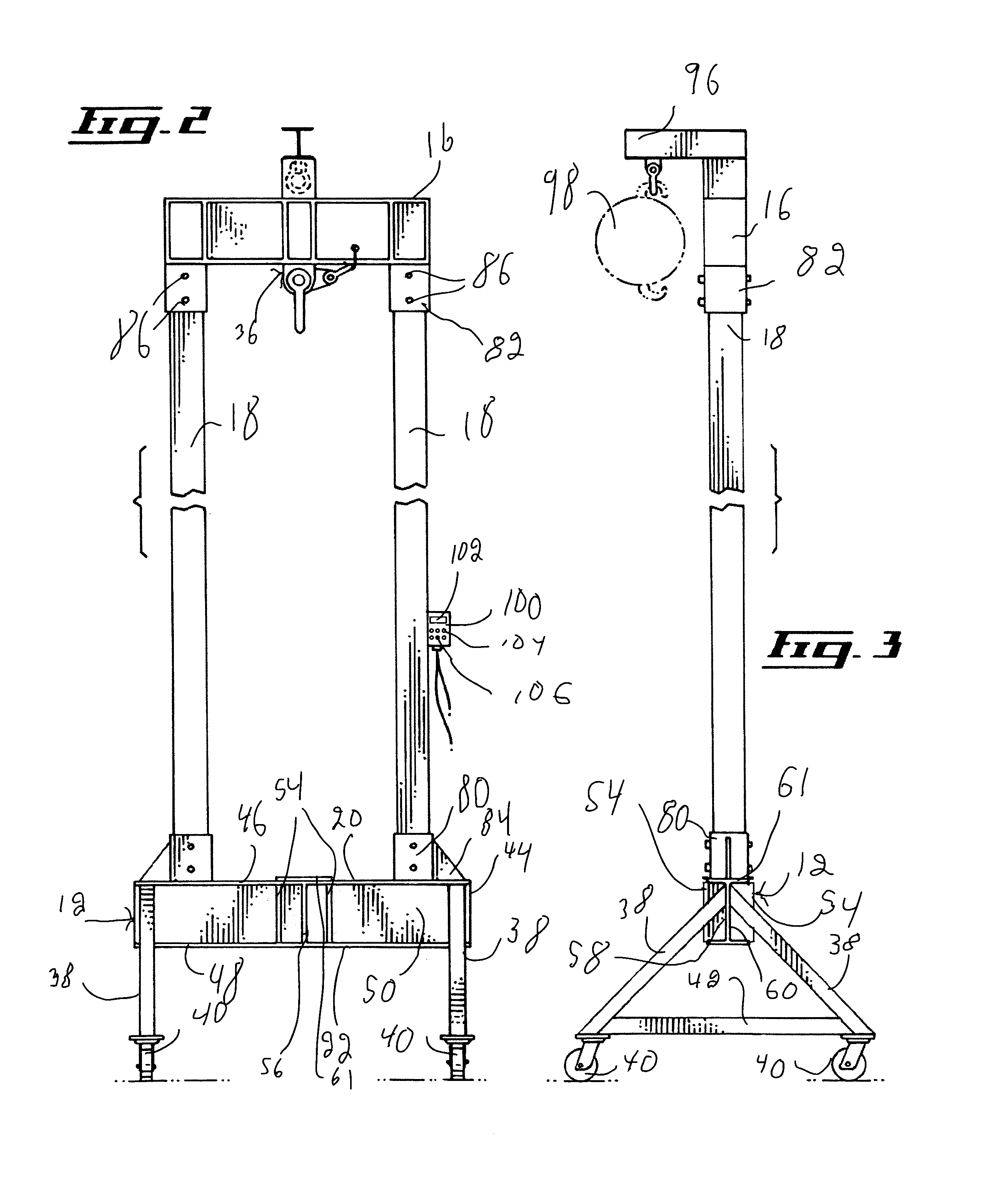
[0031]FIG. 1 illustrates a test stand 10 for allowing the testing of both a pull-type lifting apparatus and a push-type lifting apparatus. The test stand 10 includes a base 12 defining two substantially opposed base surfaces 20 and 22, a carriage component 14 slidably mounted to the base 12, a pull-type lifting apparatus receiving section 16 and two connecting members 18 connecting the base 12 and the pull-type lifting apparatus receiving section 16.

[0032]The carriage component 14 includes a load transmitting section 24 and a sensor receiving section 26. The load transmitting section 24 and the sensor receiving section 26 are spaced apart by spacing members 28.

[0033]The spacing members 28 are slidably mounted to the base 12 and allow a sliding movement of the carriage component 14 relatively to the base 12 between a retracted configuration wherein the load transmitting section is positioned substantially adjacent to the base surface 20 and an extended configuration wherein the senso...


PUM


Abstract

A test stand for allowing the testing of both a pull-type lifting apparatus and a push-type lifting apparatus. The test stand includes a base and a carriage component, the carriage component including a load transmitting section and a sensor receiving section. The load transmitting section and the sensor receiving section are spaced apart by spacing members. The spacing members are slidably mounted to the base for allowing a sliding movement of the carriage component relative to the base between a retracted configuration and an extended configuration. A load sensor provides a measurement of a force biasing the carriage component towards the extended configuration. The carriage component is configured and sized for allowing the push-type lifting apparatus to be inserted between the base and the load transmitting section so as to bias the carriage component towards the extended configuration and for allowing the attachment of the pull-type lifting apparatus to the load transmitting section so as to bias the carriage component towards the extended configuration.

Description

[0001]This application claims priority from Canadian Application Serial Number 2,470,187 filed on Jun. 5, 2004.FIELD OF THE INVENTION[0002]The present invention relates to test stands. More specifically, the present invention is concerned with a polyvalent test stand for testing a lifting apparatus.BACKGROUND OF THE INVENTION[0003]Many types of lifting apparatuses, such as hoists, are commonly used in many industries. Such apparatuses allow a user to manipulate relatively heavy loads with relatively little effort.[0004]However, these apparatuses often become damaged, either through normal use or through abuse by their users. In this case, it often happens that the apparatus becomes unsafe and becomes unable to lift a load for which it is normally rated.[0005]By their nature, the loads manipulated by lifting apparatuses are relatively heavy and can cause a lot of damages and injuries if, for any reason, the apparatus breaks and frees the load.[0006]A common type inspection performed ...

Claims


Application Information

Patent Timeline
IPC IPC(8): G01N3/02G01N3/00B66C15/00G01M99/00G01N33/00
CPCB66C15/00G01N3/02G01N2033/0078G01N2203/0246G01N2203/0623
Inventor JOUBERT, PIERRE
Owner INNOVATIONS INDS JOUBERT
Why Eureka
Try Eureka