Multiple-front combustion chamber system with a fuel/air management system

a combustion chamber and multiple-front technology, applied in the field of combustion chamber systems, can solve the problems of increasing the ignition-to-peak-pressure time and shortening the ignition-to-peak-pressure time, so as to shorten the time between spark ignition and boost the peak combustion pressure, the effect of improving fuel efficiency

Inactive Publication Date: 2005-07-05
ADAMS JOSEPH S
View PDF40 Cites 56 Cited by
  • Summary
  • Abstract
  • Description
  • Claims
  • Application Information

AI Technical Summary

Benefits of technology

[0011]My invention in one or more of its embodiments improves combustion systems of positive-displacement, spark-ignited, internal combustion engines and is of particular benefit to gas-powered linear engines of this type. The improvements include shortening the time between a spark ignition and the peak pressure obtained by combustion, bo...

Problems solved by technology

Such turbulence is known to shorten ignition-to-peak-pressure time while boosting ...

Method used


Image

  • Multiple-front combustion chamber system with a fuel/air management system
  • Multiple-front combustion chamber system with a fuel/air management system
  • Multiple-front combustion chamber system with a fuel/air management system

Examples


Embodiment Construction

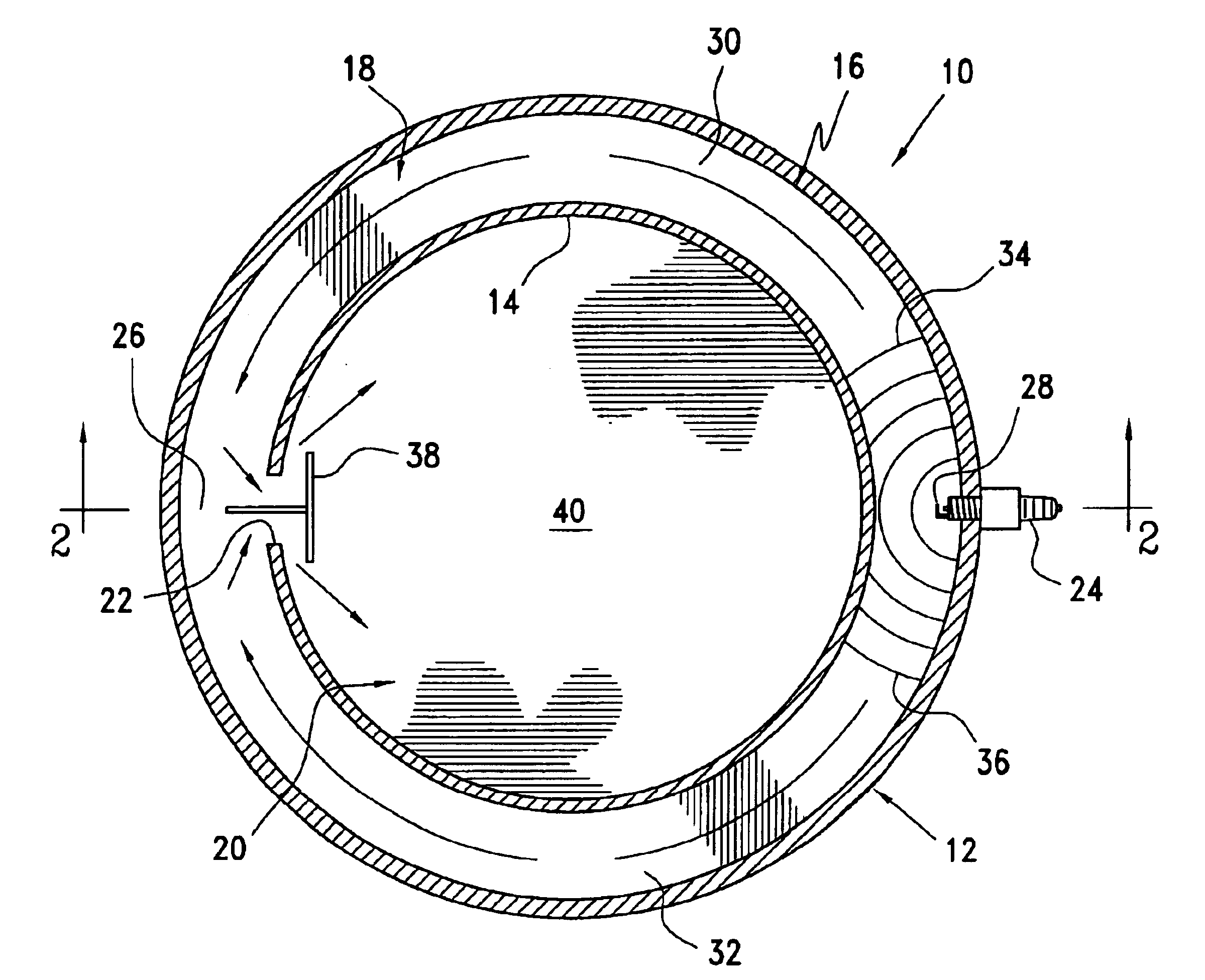
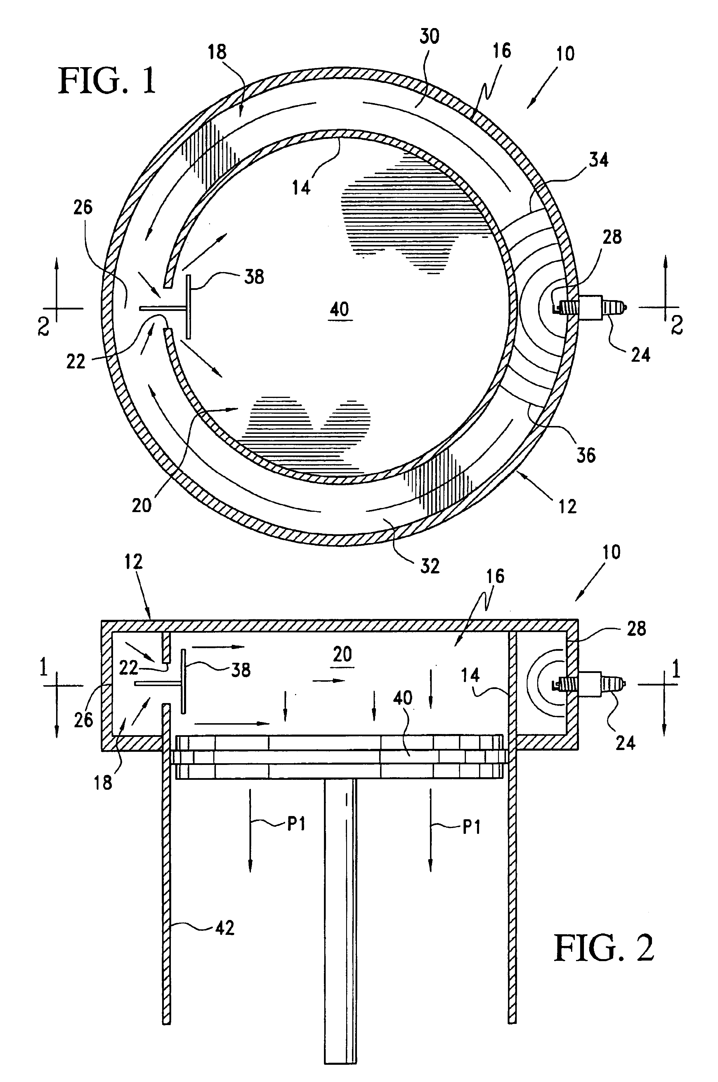
[0044]A multiple-front combustion chamber system 10 is shown in FIGS. 1 and 2 within a modified cylinder head housing 12. An annular wall structure 14 within the cylinder head housing 12 divides a combustion chamber 16 into a pre-combustion chamber 18 and a main combustion chamber 20. The wall structure 14 forms a periphery of the main combustion chamber 20 and together with the cylinder head housing 12 defines an annular space of the pre-combustion chamber 18 surrounding the main combustion chamber 20. An opening 22 formed in the wall structure 14 between the pre-combustion chamber 18 and the main combustion chamber 20 defines a proximal end 26 of the pre-combustion chamber 18. A spark-ignition device 24 extending through the cylinder head housing 12 into the pre-combustion chamber 18 is positioned diametrically opposite to the opening 22 defining the distal end 28 of the pre-combustion chamber 18.

[0045]As best seen in FIG. 1, the annular structure of the pre-combustion chamber 18 ...


PUM


Abstract

A combustion chamber of a positive-displacement spark-ignited internal combustion engine is divided into a main combustion chamber and a pre-combustion chamber having proximal and distal ends. The proximal end is connected to the main combustion chamber and a spark-ignition device is located at the distal end. Within the pre-combustion chamber, a plurality of passageways extend between its proximal and distal ends so that a flame front ignited by the ignition device at the distal end of the pre-combustion chamber propagates along the plurality of passageways as separate flame fronts toward the proximal end of the pre-combustion chamber. A displacer separates a premixing chamber from the pre-combustion and main combustion chambers. The displacer is relatively moveable for transferring the charge of fuel and air from the premixing chamber into the pre-combustion main combustion chambers.

Description

CROSS-REFERENCE TO RELATED APPLICATIONS[0001]Priority is claimed to Provisional Application No. 60 / 442,402, filed 24 Jan. 2003, the disclosure of which is hereby incorporated by reference.BACKGROUND OF THE INVENTION[0002]1. Field of the Invention[0003]The invention relates to combustion chamber systems for positive-displacement spark-ignited internal combustion engines and to displacement-type scavenging and charging systems for the purpose of replacing fuel / air mixes in the combustion chamber.[0004]2. Description of Related Art[0005]Positive-displacement spark-ignited internal combustion engines benefit by limiting the period of time between a spark ignition and a peak pressure obtained from burning fuel. In crankshaft-type engines, rapid combustion assures that more of the fuel can be burned after the top-dead-center piston position, resulting in additional horsepower and more efficient consumption of fuel. In linear engines, such as may be used for fastening tools, rapid combusti...

Claims


Application Information

Patent Timeline
IPC IPC(8): F02B19/02F02B19/16F02B19/00F02B19/12
CPCF02B19/02F02B19/12F02B19/16Y02T10/125B25C1/08Y02T10/12
Inventor ADAMS, JOSEPH S.
Owner ADAMS JOSEPH S
Why Eureka
Try Eureka