
Load limiting structure for vehicle occupant restraint system

Inactive Publication Date: 2005-07-05
KEY SAFETY SYST
View PDF15 Cites 46 Cited by
  • Summary
  • Abstract
  • Description
  • Claims
  • Application Information

AI Technical Summary

Benefits of technology

The load-limiting device provides flexibility in force dissipation, reducing the energy and force applied to occupants by absorbing kinetic energy through controlled deformation, thereby enhancing safety by distributing crash forces more effectively.

Problems solved by technology

Moreover, in those patents a crush tube is provided, and is crushed by the piston as the piston moves in one direction in the fluid chamber, to further dissipate forces applied to the piston by a vehicle occupant restraint system.

Method used


Image

  • Load limiting structure for vehicle occupant restraint system
  • Load limiting structure for vehicle occupant restraint system
  • Load limiting structure for vehicle occupant restraint system

Examples


Embodiment Construction

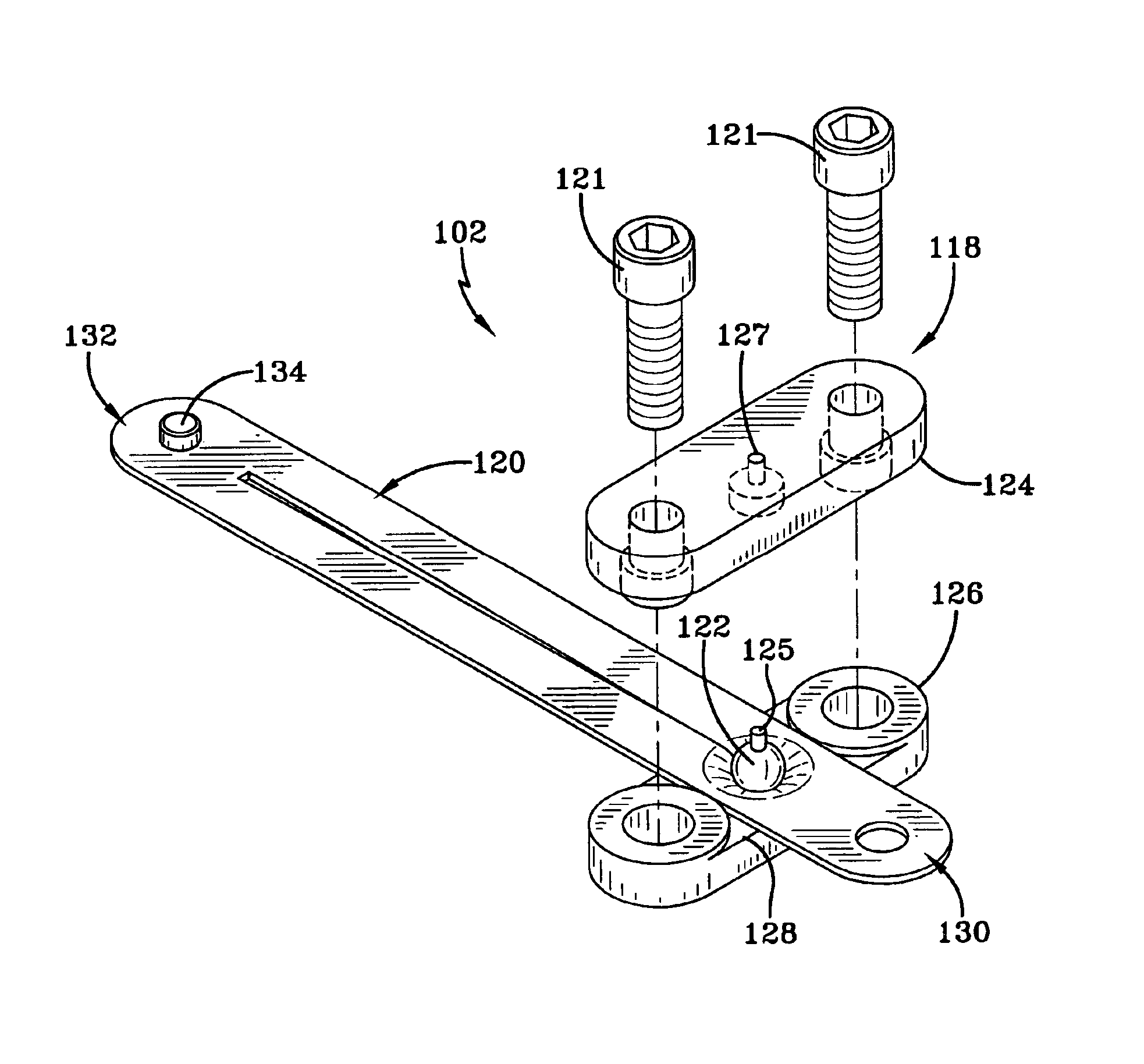
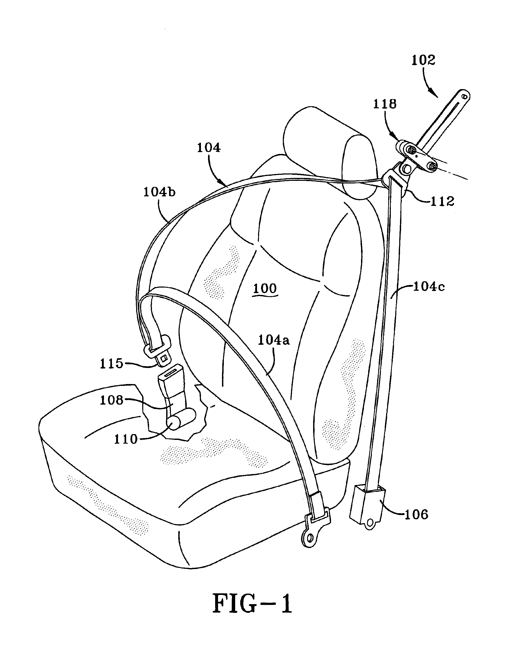
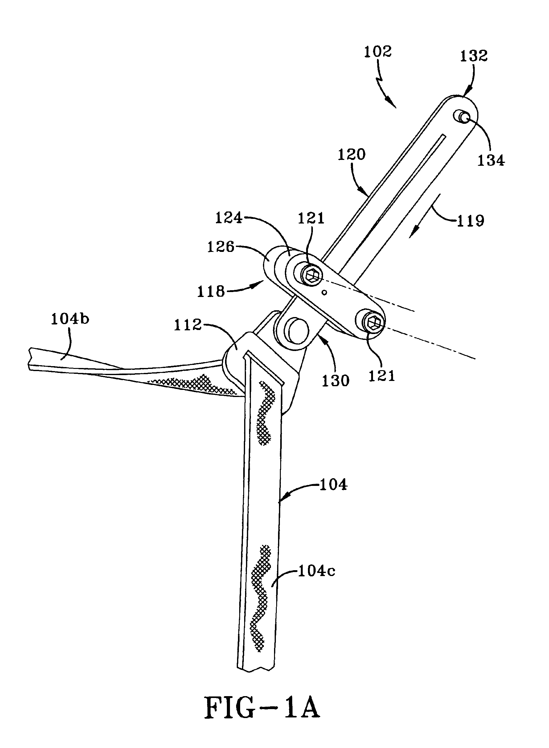
[0022]The present invention relates to a load-limiting device for a vehicle occupant restraint, which dissipates forces applied to the vehicle occupant restraint in a predetermined manner during a crash. The principles of the present invention are applicable to different configurations for a vehicle occupant restraint, and are described below in connection with a belt system that includes a lap belt and shoulder harness (which is often referred to as a three-point safety restraint system). It will be clear to those in the art the principles of the invention are applicable to a variety of vehicle occupant restraints (e.g. front and rear seat belts, etc) and are applicable to vehicle occupant restraints anchored directly to a structural part of a vehicle (e.g. a vehicle floor, B-pillar, etc.) and to vehicle restraints anchored to a vehicle seat.

[0023]FIG. 1 schematically illustrates a vehicle occupant restraint system 100, which incorporates a load-limiting device 102 according to the...


PUM


Abstract

A load-limiting device has a mechanical structure designed to dissipate forces applied by a vehicle occupant to a safety belt during a crash. The load limiting device comprises a housing and a deformable member, at least one of which is configured for connection to a vehicle safety belt and the other of which is configured for connection to a structural part of a vehicle. The housing and the deformable member are moveable relative to each other when force is applied to the one of those members. The housing supports a hardened member formed of a material which is harder than the deformable member and which is positioned to engage and deform the deformable member as the deformable member is being moved relative to the housing.

Description

FIELD OF THE INVENTION[0001]The present invention relates to a load limiting structure for a vehicle occupant restraint.BACKGROUND OF THE INVENTION[0002]A typical vehicle occupant restraint system for a vehicle comprises a belt system (often comprising a lap belt portion and a shoulder belt portion) anchored to structural parts of the vehicle such as the floor, a pillar such as a B pillar or to a seat frame. Where the restraint system includes a shoulder belt portion (also referred to herein as a “shoulder harness”), the shoulder harness typically extends through a web guide that is coupled to a structural part of the vehicle such as the B pillar or the seat frame. The restraint system further includes a retractor, often called an “ELR” or emergency locking retractor, which is designed to take up or provide a controlled amount of slack in the belt system when the belt system has been fitted about a vehicle occupant. The retractor allows payout of belt (typically the shoulder belt) i...

Claims


Application Information

Patent Timeline
Patent Type & Authority Patents(United States)
IPC IPC(8): B60R22/28
CPCB60R22/28B60R2022/286B60R2022/289
Inventor SCHULZ, KURTBAUER, BARNEY
Owner KEY SAFETY SYST
Learn More