
Stiffening arrangement for a forward structure of a motor vehicle

a technology for forward structures and motor vehicles, which is applied in the direction of superstructures, superstructure subunits, and understructures, can solve the problems of inevitability of forward structure deformation, and achieve the effect of improving the vibrational comfort of the driver and the forward structur

Active Publication Date: 2017-02-14
DR ING H C F PORSCHE AG
View PDF12 Cites 0 Cited by
  • Summary
  • Abstract
  • Description
  • Claims
  • Application Information

AI Technical Summary

Benefits of technology

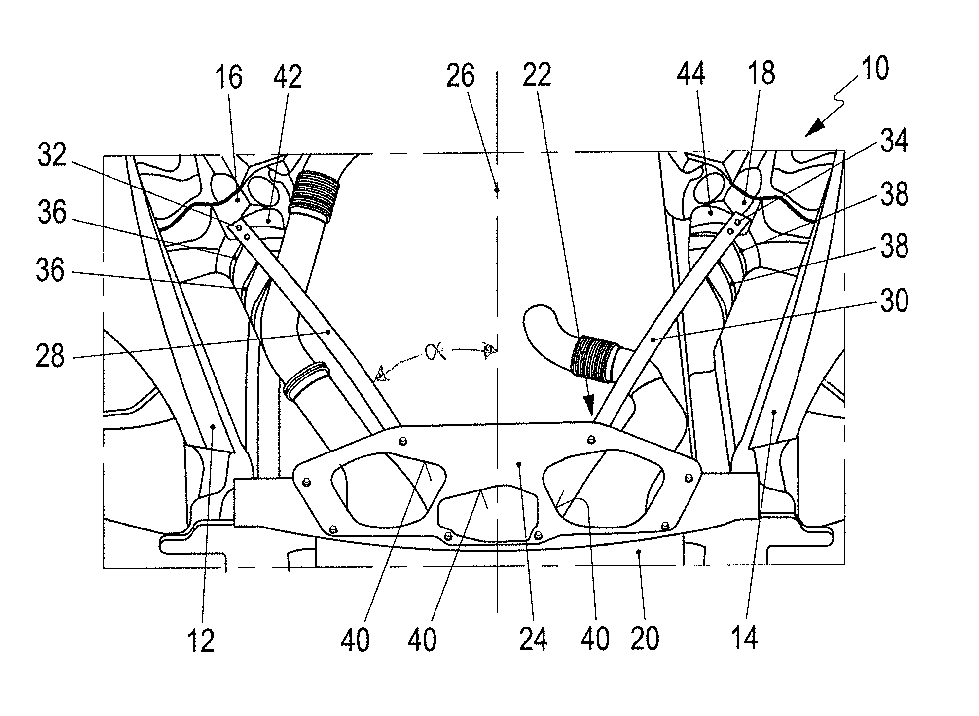
[0009]The mounting bracket may be connected by a right connecting strut to a right longitudinal member and / or by a left connecting strut to a left longitudinal member. The right longitudinal member and the left longitudinal member may be part of a load-bearing support structure of the motor vehicle body of the motor vehicle. The left suspension-strut dome may be connected to the left longitudinal member, and / or the right suspension-strut dome may be connected to the right longitudinal member. The mounting bracket, the shear field and the stiffening struts thus form cooperate with the longitudinal members to form a ring structure via which forces can be dissipated. The functional elements of the stiffening arrangement thus form a stiffening frame via which forces of intense loads can be dissipated without damaging engine components of a motor vehicle engine that are arranged within the ring-like frame. Vibrations of the forward structure can be prevented to a correspondingly greater extent, thereby improving vibrational comfort for a driver of the motor vehicle.
[0018]The right stiffening strut may be fastened to the right suspension-strut dome by a right connecting means that is oriented substantially in vertically, and the left stiffening strut may be fastened to the left suspension-strut dome by a left connecting means that is oriented substantially vertically. The fastening of the stiffening struts to the respectively associated suspension-strut dome during the assembly process can thereby be simplified. In particular, the fastening can be performed by an assembly robot.

Problems solved by technology

Forces that act in the event of a crash are so intense that deformation of components of the forward structure is inevitable.

Method used


Image

  • Stiffening arrangement for a forward structure of a motor vehicle
  • Stiffening arrangement for a forward structure of a motor vehicle

Examples


Embodiment Construction

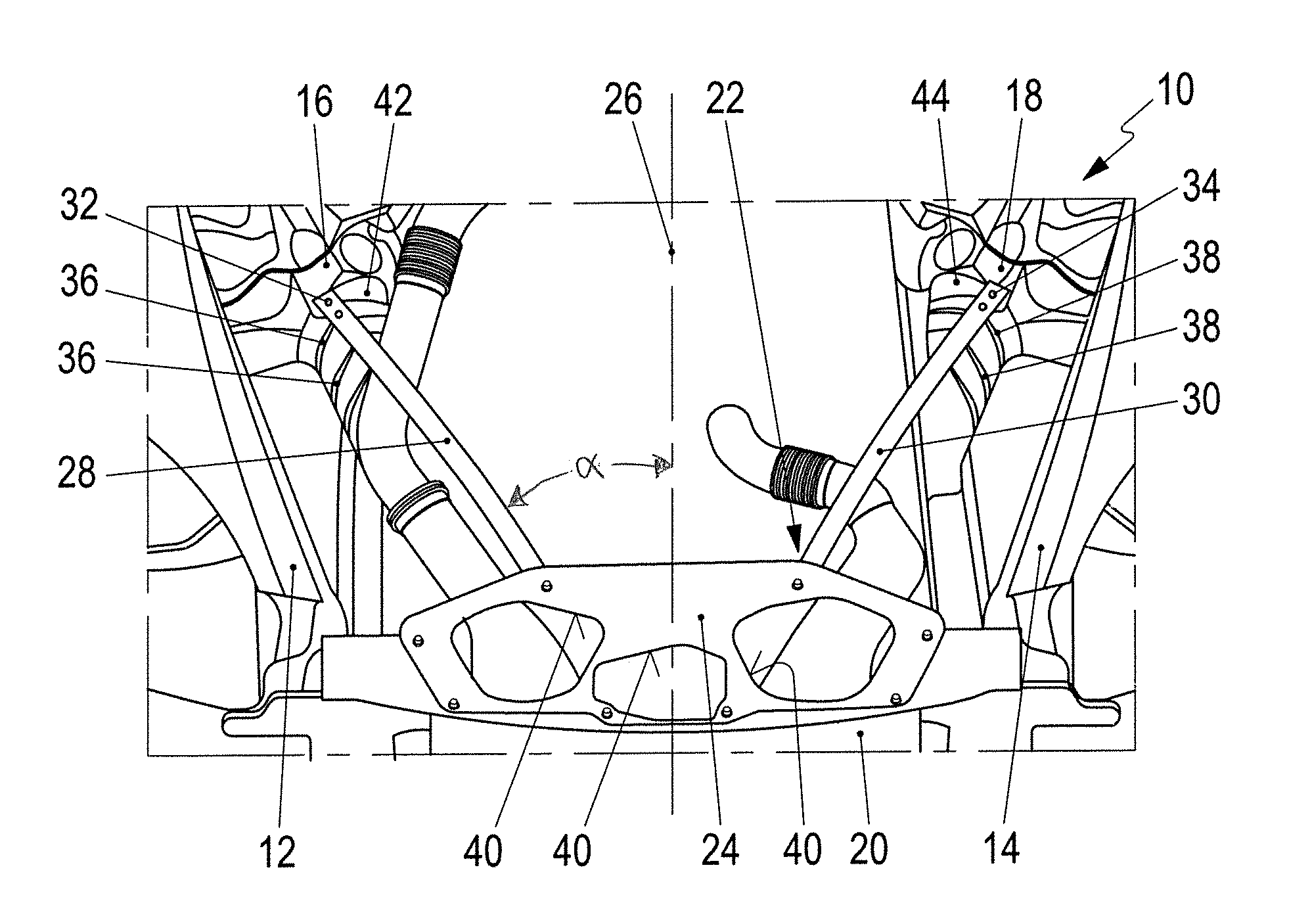
[0022]The forward structure 10 illustrated in FIG. 1 has a right longitudinal member 12 and a left longitudinal member 14. A left suspension-strut dome 16 is connected to the left longitudinal member, whereas a right suspension-strut dome 18 is connected to the right longitudinal member. A mounting bracket 20 of a stiffening arrangement 22 is connected to the right longitudinal member 12 and to the left longitudinal member 14.

[0023]The stiffening arrangement 22 has a shear field 24 that is connected to the mounting bracket 20 and to which, in turn, there are connected right and left stiffening struts 28, 30 that run substantially diagonally with respect to a longitudinal direction 26, The right stiffening strut 28 of the stiffening arrangement 22 is connected to the right-hand suspension-strut dome 16 by way of vertically running right connecting element 32. The left stiffening strut 30 of the stiffening arrangement 22 is connected to the left suspension-strut dome 18 by way of vert...


PUM


Abstract

A stiffening arrangement (22) for a forward structure (10) of a motor vehicle has a mounting bracket (20) for mounting a motor vehicle radiator. A shear field (24) is connected to the mounting bracket (20) to dissipate shear forces. A right stiffening strut (28) connects the shear field (24) to a right suspension-strut dome (16) and supports the mounting bracket (20) on the right suspension-strut dome (16), and a left stiffening strut (30) connects the shear field (24) to a left suspension-strut dome (18) and supports the mounting bracket (20) on the left suspension-strut dome (18). Thus, a major part of the crumple zone of the forward structure (10) provided for a frontal crash can be utilized, so that the risk of damage to engine components in an engine bay of the forward structure (10) is reduced and vibrational comfort for the driver is improved.

Description

CROSS REFERENCE TO RELATED APPLICATION[0001]This application claims priority under 35 USC 119 to German Patent Appl. No. 10 2014 111 794.8 filed on Aug. 19, 2014, the entire disclosure of which is incorporated herein by reference.BACKGROUND[0002]1. Field of the Invention[0003]The invention relates to a stiffening arrangement for a forward structure of a motor vehicle for preventing damage to engine components in an engine bay of the forward structure in the event of a crash, and / or for preventing vibrations of the forward structure to improve vibrational comfort.[0004]2. Description of the Related Art[0005]U.S. Pat. No. 7,766,420 discloses a bracket for a radiator grille to be supported by obliquely running supporting struts on suspension-strut domes of a forward structure of a motor vehicle.[0006]There is a constant demand to prevent damage to engine components in an engine bay of the forward structure and to improve vibrational comfort for the driver.[0007]Objects of the invention...

Claims


Application Information

Patent Timeline
Patent Type & Authority Patents(United States)
IPC IPC(8): B62D21/15B62D21/11B62D25/08
CPCB62D21/152B62D21/11B62D25/082
Inventor JOEST, RAINERPETROVICS, JOZSEFBECHTLER, FRANKPFLUEGER, JOCHENKRIENER, PHILIPP
Owner DR ING H C F PORSCHE AG
Learn More