Drum brake and brake shoe

a technology of drum brakes and shoes, applied in the direction of drum brakes, braking elements, braking members, etc., can solve the problem that the lining no longer passes into the full surface, and achieve the effect of dissipating the forces

Active Publication Date: 2018-09-06
SAF HOLLAND GMBH
View PDF7 Cites 0 Cited by
  • Summary
  • Abstract
  • Description
  • Claims
  • Application Information

AI Technical Summary

Benefits of technology

[0019]Expediently, the first contact face is configured as a friction face of the shell region and the second contact face is configured as a friction face of the friction lining. The friction faces therefore serve to dissipate the forces which occur on account of the rotation of the brake drum with respect to the brake shoe into frictional and thermal energy. In other words, the first contact face and the second contact face therefore form a frictional pairing.
[0020]The brake shoe is expediently mounted such that it can be pivoted with respect to the rotational axis. For this purpose, a brake carrier is provided which forms a mount for the brake shoe. The brake shoe can be pivoted or tilted with respect to the brake carrier, with the result that its angle can be changed, as viewed in the pivoting plane, in order to actuate the drum brake. The brake shoe can particularly advantageously also be pivoted or tilted in the radial plane, with the result that the angle with respect to the rotational axis can be changed.

Problems solved by technology

It is a problem in drum brakes of this type, however, that, upon actuation of the drum brake, the open region of the brake drum which does not have the attaching region for mounting on the wheel hub expands on account of thermal influence, with the result that the brake linings no longer pass into full surface contact with the brake drum.

Method used


Image

  • Drum brake and brake shoe
  • Drum brake and brake shoe
  • Drum brake and brake shoe

Examples


Embodiment Construction

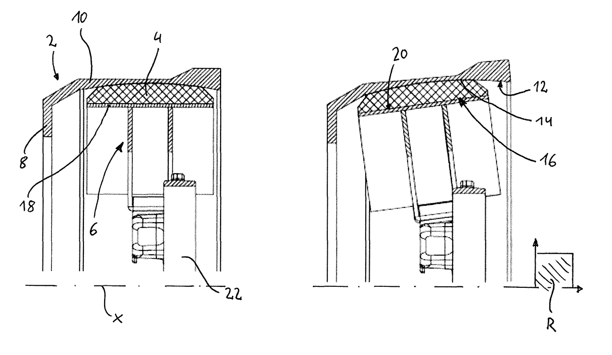
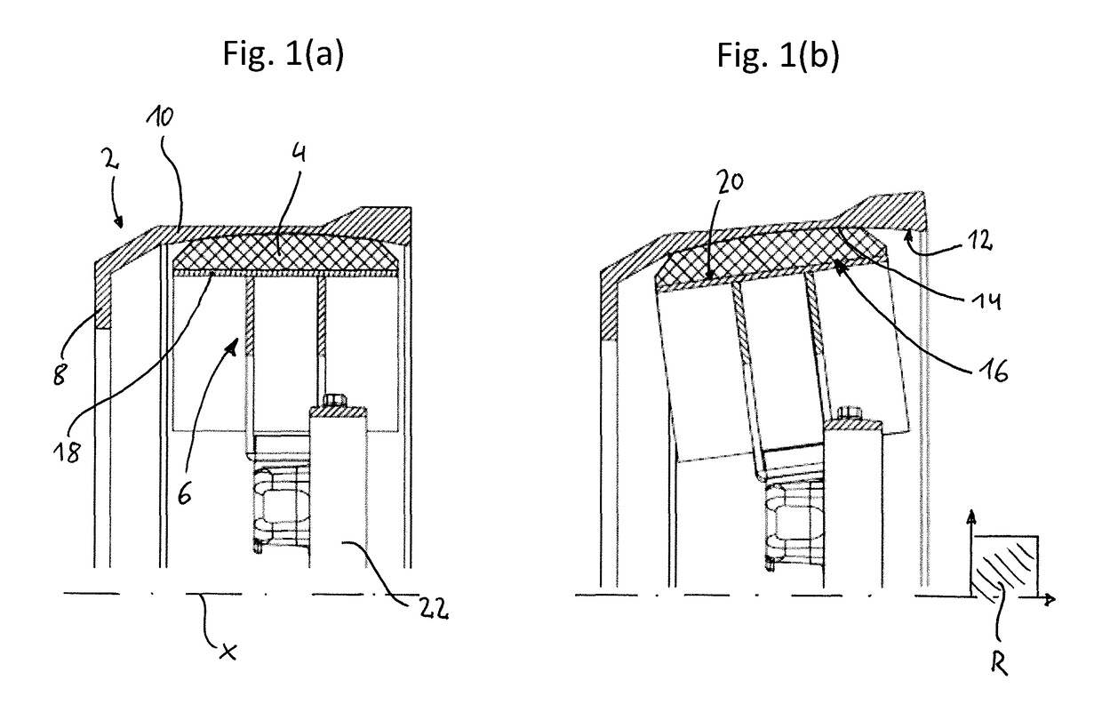
[0031]FIGS. 1(a) and 1(b)show two cross-sectional views in the radial plane of the first, preferred embodiment of the drum brake according to the invention. Here, FIG. 1(a) shows the drum brake in the cold state, and FIG. 1(b) shows the drum brake in the case of thermal expansion, that is to say in the actuated state. The drum brake comprises a brake drum 2, a friction lining 4 and a brake shoe 6.

[0032]The brake drum has an attaching region 8 for arranging the brake drum 2 on a vehicle part, such as an axle element or a wheel hub. Here, the attaching region expediently extends in the radial direction, but at least with a component in the radial direction. In a manner which adjoins the attaching region 8, the brake drum 2 has a shell region 10 which configures substantially the shape of a hollow cylinder. On its inner circumference, the shell region 10 has a first contact face 12.

[0033]The friction lining 4 has a second contact face 14 which faces the shell region 10, in particular t...


PUM


Abstract

A drum brake includes a brake drum with an attaching region for arranging the brake drum on a vehicle part, such as a wheel hub, and a shell region with a first contact face, and a friction lining with a second contact face which faces toward the shell region, the first and second contact face being curved along or in a radial plane.

Description

BACKGROUND OF THE INVENTION[0001]The present invention relates to a drum brake and to a brake shoe of a drum brake, both in particular for commercial vehicles, such as trucks, semitrailers, trailers or the like.[0002]Drum brakes of the type under discussion here are well known from the prior art. Here, a brake drum is provided, in the interior of which two brake shoes are mounted pivotably, and the brake shoes are pressed via a cam roller and a camshaft onto the inner circumferential face of the brake drum. It is a problem in drum brakes of this type, however, that, upon actuation of the drum brake, the open region of the brake drum which does not have the attaching region for mounting on the wheel hub expands on account of thermal influence, with the result that the brake linings no longer pass into full surface contact with the brake drum.[0003]It is therefore an object of the present invention to provide a drum brake and a brake shoe of a drum brake, in particular for commercial ...

Claims


Application Information

Patent Timeline
Patent Type & Authority Applications(United States)
IPC IPC(8): F16D51/10F16D65/22F16D65/09F16D65/08F16D65/10
CPCF16D51/10F16D65/22F16D65/09F16D65/08F16D65/10F16D2065/134F16D69/0416F16D2065/1308F16D2051/008F16D2065/026F16D51/20F16D2065/1324F16D2069/0441
Inventor ARPACI, MUHAMMETSTEGMANN, RAINERWEBER, ELMAR
Owner SAF HOLLAND GMBH
Why Eureka
Try Eureka