Rotary movement converting mechanism and measuring instrument

a technology of converting mechanism and converting mechanism, which is applied in the direction of mechanical measuring arrangement, measuring device, instruments, etc., can solve the problems of unfavorable smooth movement of spindle and measurement error, and achieve the effect of improving the stability of the measuring instrument, preventing the displacement of the top member provided inside the measuring instrument, and not increasing the pressure on the workpi

Active Publication Date: 2005-07-12
MITUTOYO CORP
View PDF10 Cites 15 Cited by
  • Summary
  • Abstract
  • Description
  • Claims
  • Application Information

AI Technical Summary

Benefits of technology

[0007]An object of the present invention is to provide a rotary movement converting mechanism and a measuring instrument capable of restraining a minute displacement of a movable body when a load is applied on a linear movement of the movable body.

Problems solved by technology

The spindle is also displaced in accordance with the minute displacement of the top member, which results in a measurement error.
Since the clearance facilitates the movement of the engaging member, if the clearance is eliminated, the spindle is not smoothly moved on account of strong abrasion between the spiral groove and the engaging member.

Method used


Image

  • Rotary movement converting mechanism and measuring instrument
  • Rotary movement converting mechanism and measuring instrument
  • Rotary movement converting mechanism and measuring instrument

Examples


first embodiment

[First Embodiment]

(1) External Structure

[0033]A first embodiment of the present invention will be described below with reference to the attached drawings.

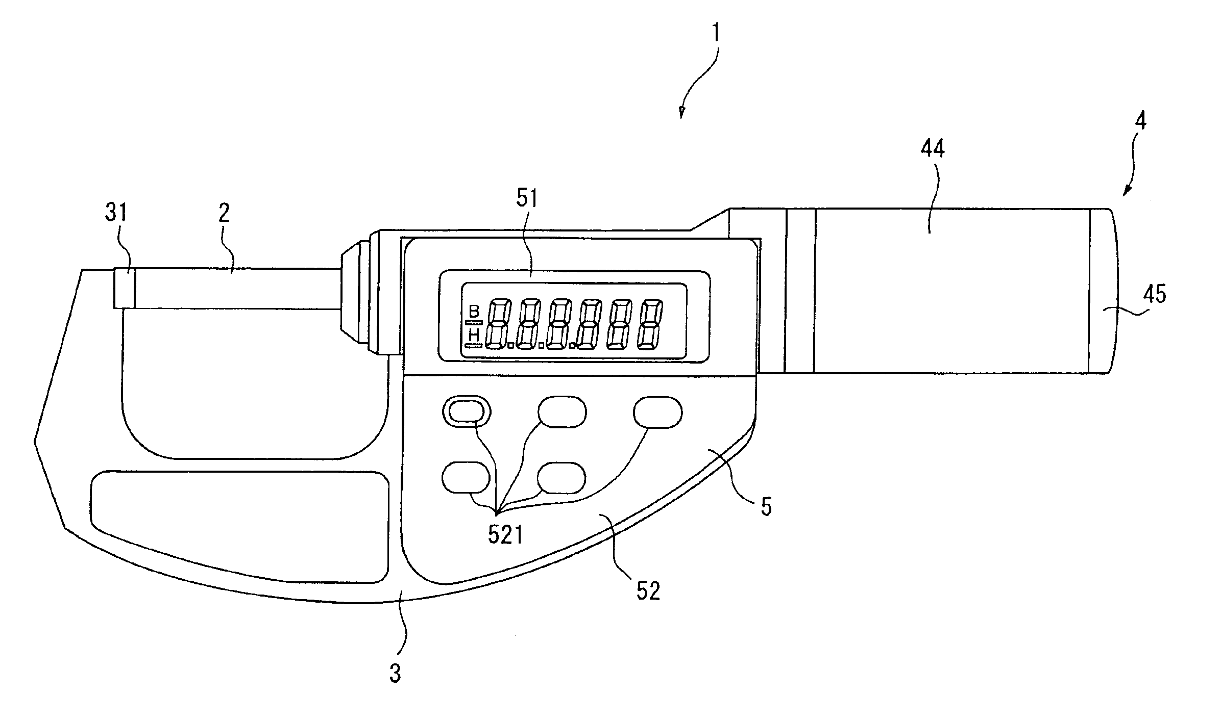
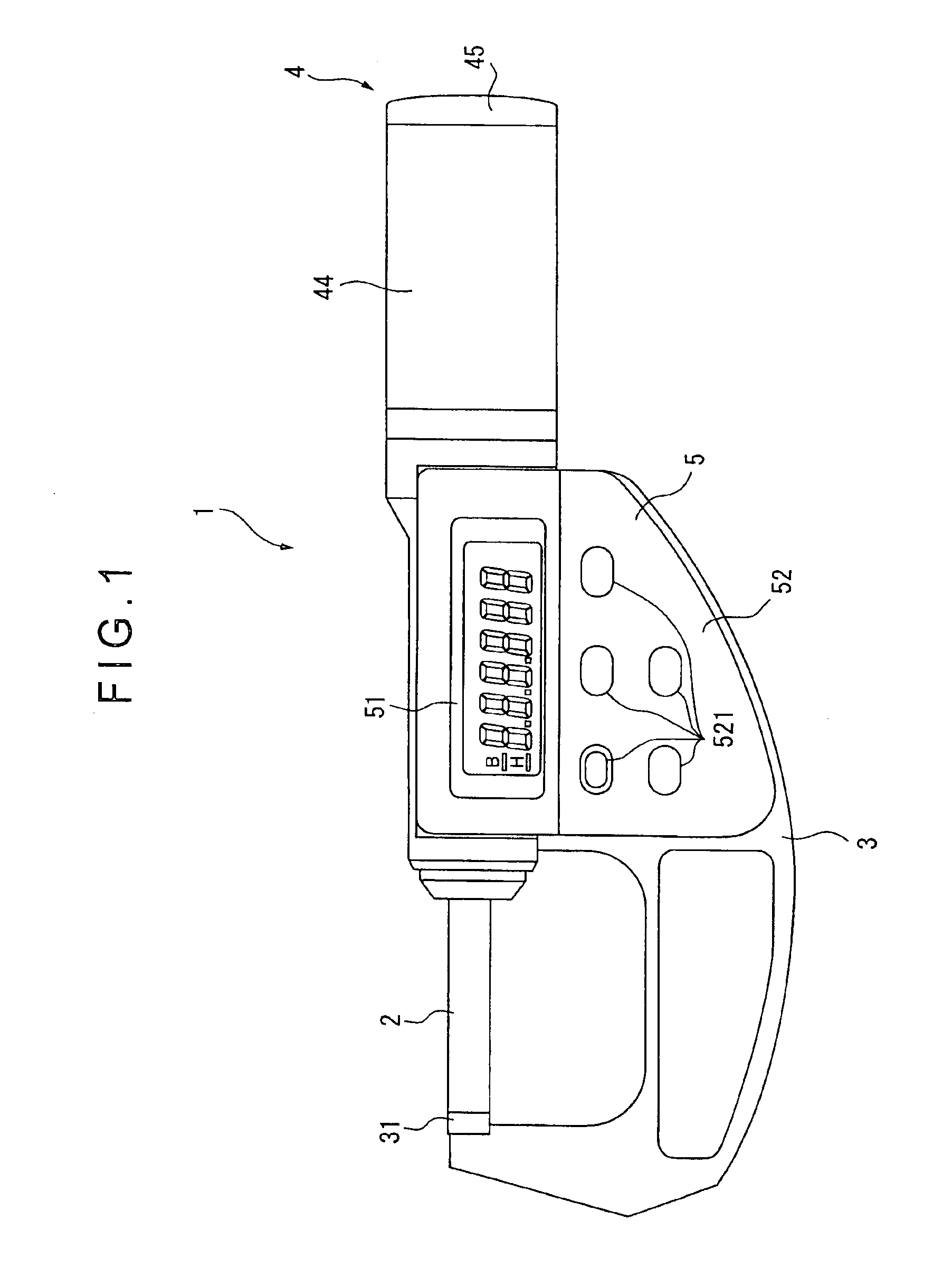
[0034]FIG. 1 is a front elevational view showing a digital-display micrometer as a measuring instrument of the first embodiment. In FIG. 1, a body 1 has a sealed internal structure and a spindle 2 (movable body) is attached to the body 1 in a projectable and retractable manner. The body 1 has a body frame 3 having approximately U-shaped cross section, and a spindle drive mechanism 4 (rotary movement converting mechanism) for advancing and retracting the spindle 2 in the axial direction thereof.

[0035]A detector (not shown) for detecting the displacement of the spindle 2 is provided inside the body frame 3 and a lid 5 is provided on the front side of the body frame 3. The detector is an electrostatic encoder, of which basis for measurement is a general one such as shown in Japanese Patent Publication No. Sho 64-11883 and Swedish Pate...

second embodiment

[Second Embodiment]

[0063]Next, a digital-display micrometer as a measuring instrument according to a second embodiment of the present invention will be described below. The digital-display micrometer of the second embodiment has approximately the same arrangement as the digital-display micrometer shown in the first embodiment except for the arrangement and function of the spindle drive mechanism. In the following description, the same reference numeral will be attached to the components identical with or similar to the above-described components to omit description thereof.

[0064]FIG. 5 are illustrations showing a spindle drive mechanism 8 of the digital-display micrometer according to the second embodiment, in which FIG. 5(A) is a cross section showing the spindle drive mechanism 8 and FIG. 5(B) is a plan view showing a primary portion of the spindle drive mechanism 8. Incidentally, FIG. 5(B) is an illustration showing the primary portion of the spindle drive mechanism 8 from the lo...


PUM


Abstract

A rotary movement converting mechanism for converting a rotary movement of a rotary body (43) into a linear movement of a movable body (2) has a support body (42) fixed to a body frame (3) and provided with a slit (42A) along an axial direction of the rotary body (43), a spiral groove (43A) formed on the inner circumference of the rotary body (43), and a top member (41) provided on the movable body (2). The top member (41) has an engaging member (41 A) inserted through the slit (42A) and having a tip end engaged with the spiral groove (43A), and a stop member (41C) for stopping the linear movement of the movable body (2) when a load is applied on the linear movement of the movable body (2). Accordingly, when a load is applied on the linear movement of the movable body (2), the linear movement is stopped and the minute displacement of the movable body (2) is restrained, thereby enhancing the stability of a measuring instrument in measuring a workpiece.

Description

BACKGROUND OF THE INVENTION[0001]1. Field of the Invention[0002]The present invention relates to a rotary movement converting mechanism for converting a rotary movement of a rotary body into a linear movement of a movable body, and a measuring instrument for measuring a displacement of a spindle in a linear direction.[0003]2. Description of Related Art[0004]Conventionally, a micrometer has been used as a measuring instrument for measuring a dimension of a workpiece by measuring a linear displacement of a spindle with an end of the spindle being abutted to the workpiece (see U.S. Pat. No. 5,495,677, FIG. 3).[0005]The micrometer shown in the U.S. Pat. No. 5,495,677 has an inner sleeve fixed on a body frame, an outer sleeve provided on the outer circumference of the inner sleeve, a spindle, and a top member attached to the spindle. The spindle works as a support body having an end fixed to the body frame and a slit is formed on the circumference thereof along the moving direction of th...

Claims


Application Information

Patent Timeline
Patent Type & Authority Patents(United States)
IPC IPC(8): G01B3/18G01B5/02
CPCG01B3/18
Inventor HAYASHIDA, SHUUJIFUJIKAWA, YUJISAITO, OSAMUSUZUKI, MASAMICHI
Owner MITUTOYO CORP
Why Eureka
Try Eureka