Overlay management system

a management system and overlay technology, applied in the field of overlay management system, can solve the problems of destroying the retroreflective film on the face of the sign behind, difficult to remove the overlay, so as to facilitate the removal of the overlay, maintain the gripping force, and facilitate the removal of the inactive sign.

Inactive Publication Date: 2005-07-12
ORAFOL AMERICAS
View PDF15 Cites 7 Cited by
  • Summary
  • Abstract
  • Description
  • Claims
  • Application Information

AI Technical Summary

Benefits of technology

[0003]The present invention is directed to an overlay system which eliminates these problems for signs made of any material. The overlay of this invention can be made of any relatively thin but tough and durable material, such as polycarbonate. In alternative embodiments, the overlay can include sheet metal, wood, fabric, fabric reinforced polyvinyl chloride, plastic, or polymeric film. The thinness of the overlay makes stacking of inactive signs much easier. This thinner overlay is attached to the main sign with refastenable fasteners which makes it much easier to remove. These fasteners can be made of any material which is suitably elastic or has such a structure that it can maintain gripping force when compressed into an appropriately sized hole. When the overlay is not needed on the front surface of the sign, it can easily be attached to the back surface of the sign for purposes such as storage. When the main sign is of an appropriate thickness, the fasteners do not protrude out the back of the sign to destroy the costly retroreflective film of another sign when stacked for storage. This method of attachment is particularly useful when the main sign is of a hollow-type construction.

Problems solved by technology

This added piece of plywood nailed to the surface of the original sign creates several problems.
First, it is difficult to remove the overlay when the overlay is not needed.
The extra thickness of the overlay creates difficulty when trying to stack many signs together.
Furthermore, when several signs are stacked against each other, the bent over nails on the back of the sign with the overlay, destroys the costly retroreflective film on the face of the sign behind it.

Method used


Image

  • Overlay management system
  • Overlay management system
  • Overlay management system

Examples


Embodiment Construction

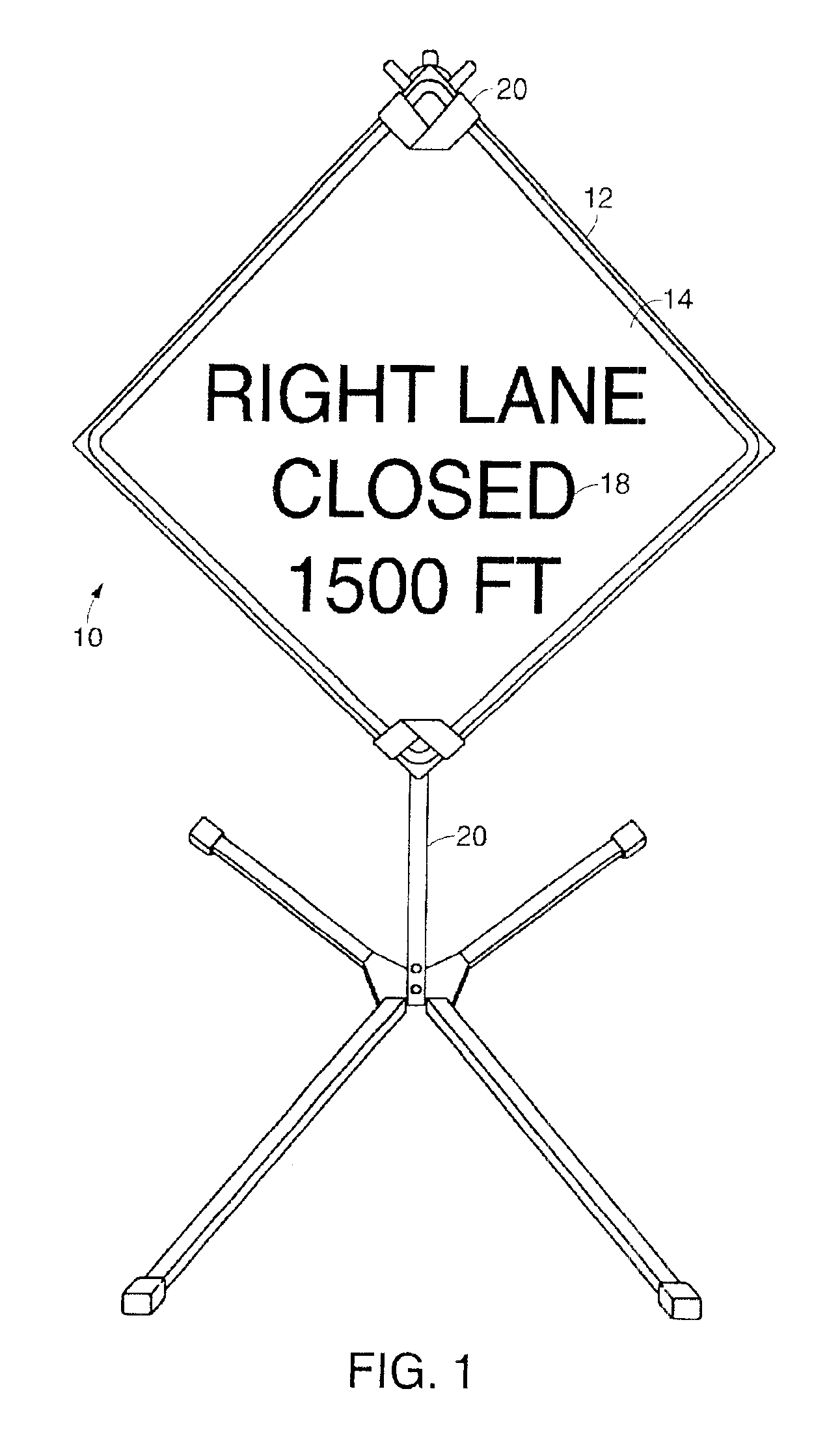
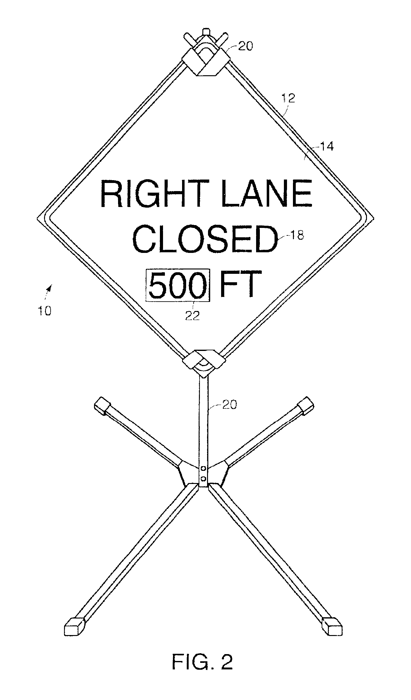
[0021]A description of preferred embodiments of the invention follows. FIG. 1 illustrates a sign 10 which includes a main body 12 that can have retroreflective sheeting 14 on a first or front surface 16 (shown in cross-sectional view in FIG. 3). The sign 10 includes lettering, images, or other indicia 18 used to convey a message, for example, to a passing motorist. In one embodiment, the sign 10 is mounted in place by a mounting device 20. FIG. 2 illustrates the sign 10 having an overlay 22 positioned over at least a portion of the main body 12 for changing all or some of the indicia 18.

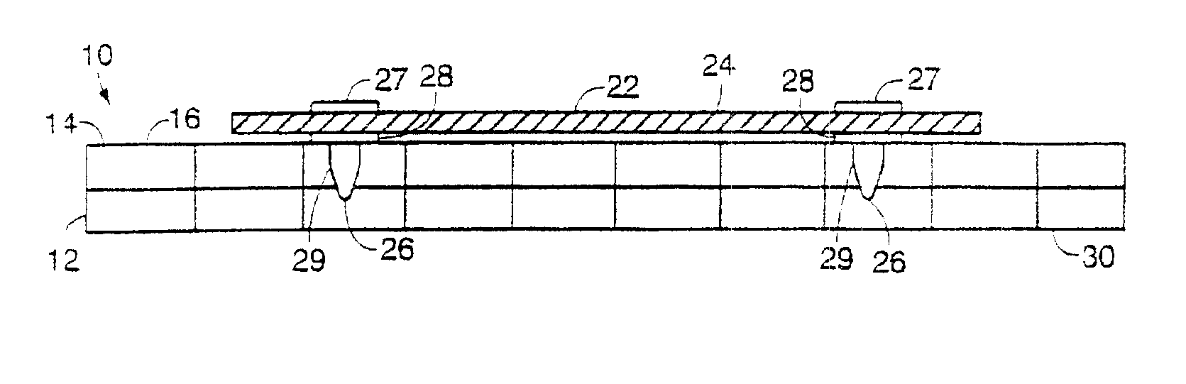
[0022]FIG. 3 is a cross-sectional view of the sign 10. In one embodiment, the main body 12 and overlay 22 are made from a tough, durable thermoplastic which is also substantially resistant to degradation to outdoor ultraviolet exposure. In this embodiment, the components 12, 22 are formed from polycarbonate. Having all of the main components made of the same material reduces the impact of temperature...


PUM


Abstract

A sign includes a main body having a first surface and a second surface and an overlay removably attachable to the first surface or the second surface of the main body, and at least two fasteners attached to the overlay for removably securing the overlay to the first surface or the second surface. Each fastener can pass through an oversized hole in the overlay and be movably secured to the overlay with a washer. Each washer spaces the overlay from the main body when the overlay is attached to the main body. The main body can include a plurality of hollow cells within the main body.

Description

RELATED APPLICATION[0001]This application claims the benefit of U.S. Provisional Application No. 60 / 213,012, filed on Jun. 21, 2000, the entire teachings of which are incorporated herein by reference.BACKGROUND OF THE INVENTION[0002]Traditionally, many temporary construction work zone or traffic control signs are made of ⅝ inch to ¾ inch (16 to 19 millimeter) plywood. With such a material, the traditional method of changing a message is with an overlay, which changes at least a portion of the message, is to simply nail another piece of plywood over the original message and bend the nails over on the back side of the sign. This added piece of plywood nailed to the surface of the original sign creates several problems. First, it is difficult to remove the overlay when the overlay is not needed. Since the overlay is not easily removed, it stays with the sign when not in use. The extra thickness of the overlay creates difficulty when trying to stack many signs together. Furthermore, whe...

Claims


Application Information

Patent Timeline
Patent Type & Authority Patents(United States)
IPC IPC(8): G09F15/00
CPCG09F15/0056
Inventor LAVOIE, MARK M.
Owner ORAFOL AMERICAS
Why Eureka
Try Eureka