Method for packing a product using a flat tubular package

Inactive Publication Date: 2005-07-12
GD SPA
7 Cites 25 Cited by

AI-Extracted Technical Summary

Problems solved by technology

Known boxing machines of the type described above are fairly bulky, and require that the stack of flat tubular packages be l...

Benefits of technology

[0005]It is an object of the present invention to provide a method of packing a product using a flat tubular pack...

Abstract

A method and machine for packing a group of cartons of cigarettes using a flat tubular package, whereby a top wall of the flat tubular package is engaged by suction by a gripping head, which is then moved to feed the flat tubular package to a seat which engages a bottom wall of the flat tubular package by suction; a relative rotation movement is then produced between the seat and the gripping head to convert the tubular package from the flat configuration to an open configuration; the group of cartons of cigarettes is pushed inside the open tubular package; the gripping head releases the top wall of the open tubular package; and the seat is moved to feed the tubular package to a closing station where the tubular package is closed.

Application Domain

Technology Topic

Image

  • Method for packing a product using a flat tubular package
  • Method for packing a product using a flat tubular package
  • Method for packing a product using a flat tubular package

Examples

  • Experimental program(1)

Example

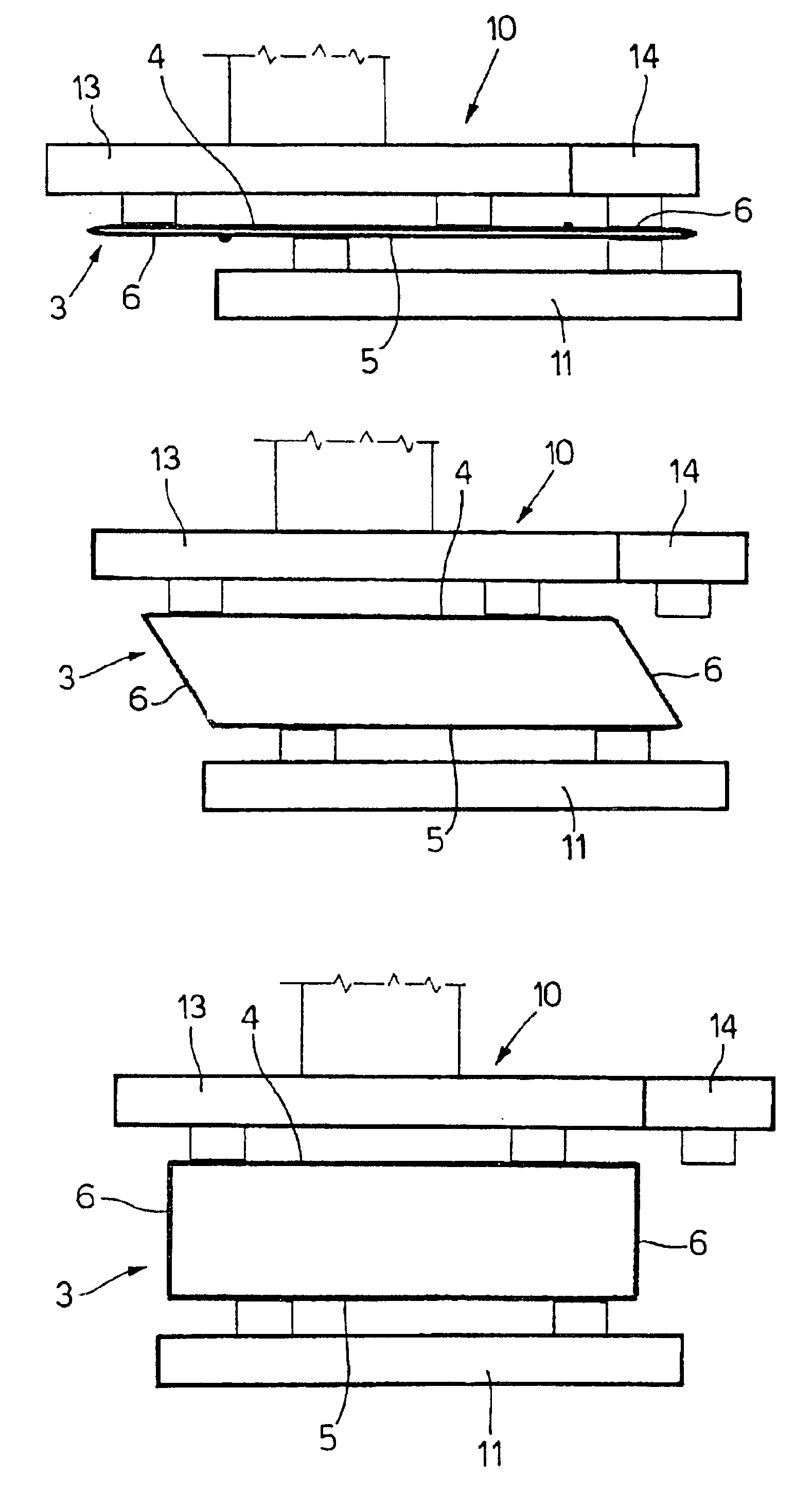
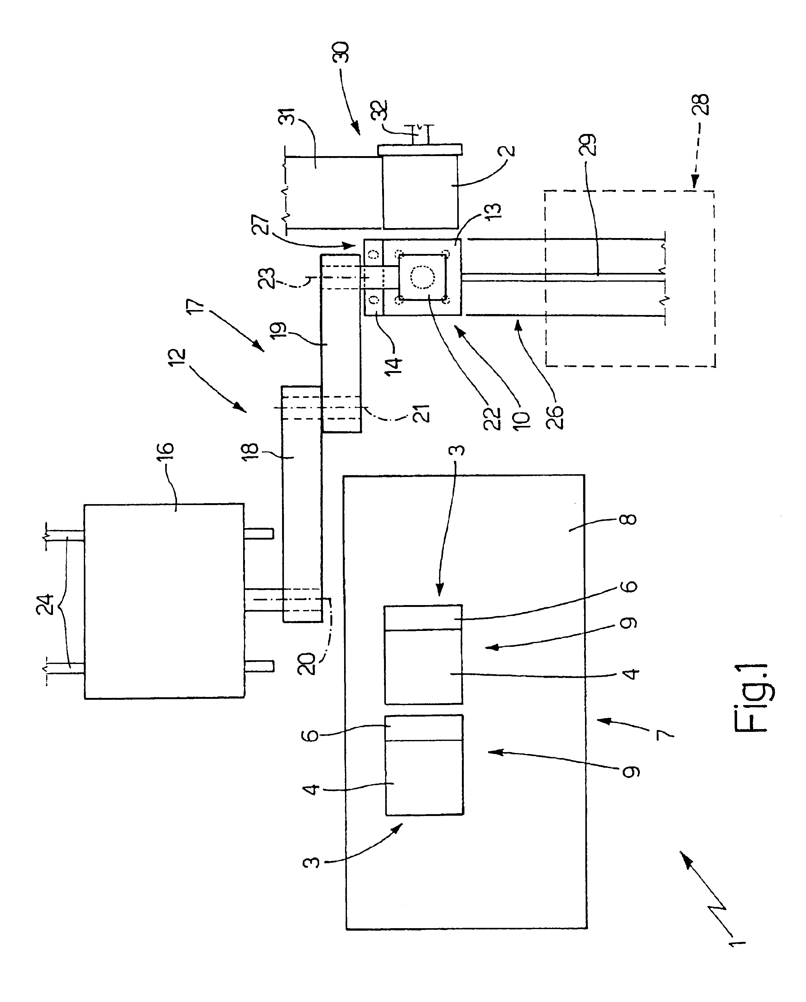
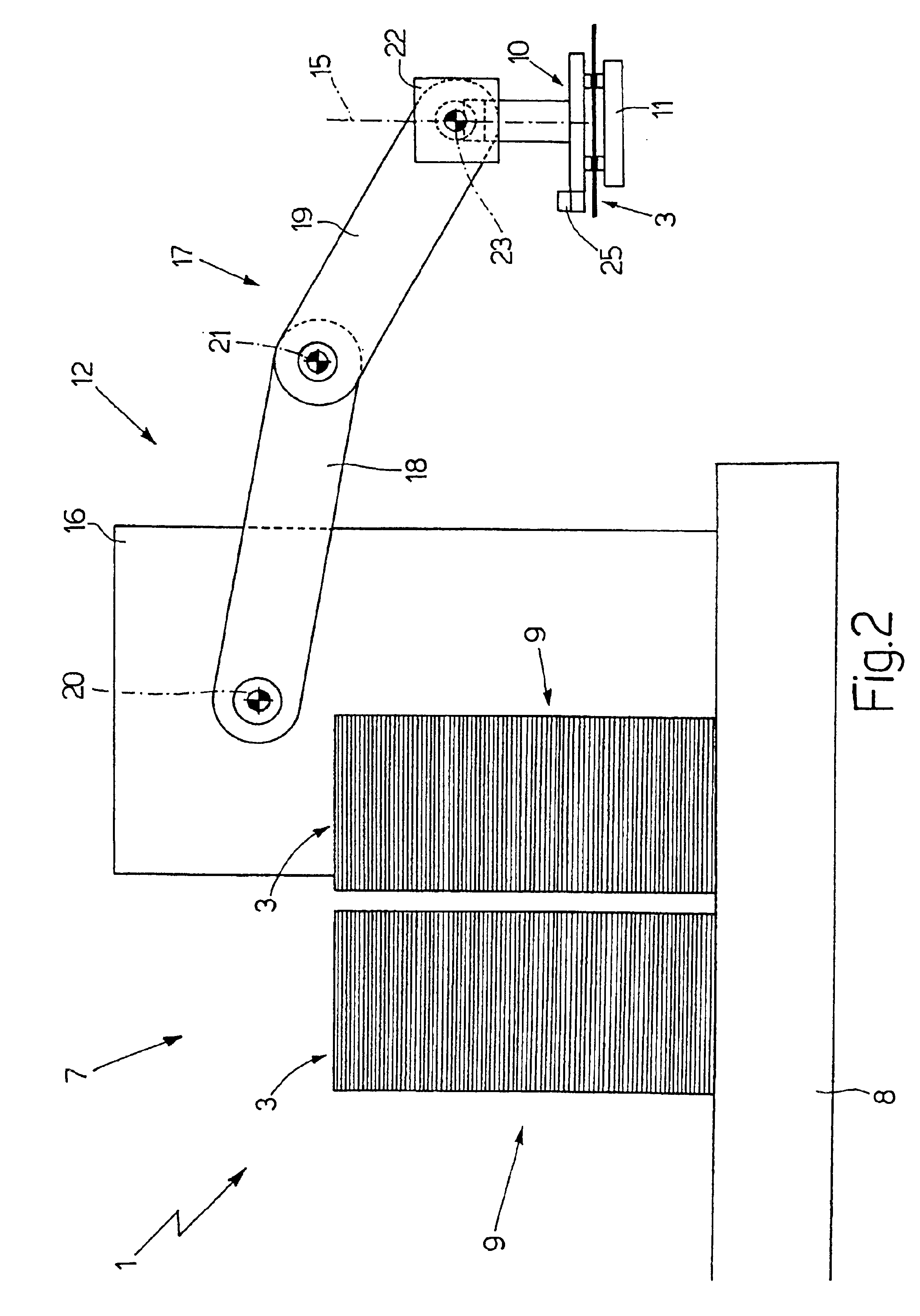
[0016]Number 1 in FIG. 1 indicates as a whole a boxing machine for boxing groups 2 of cartons of cigarettes; which machine 1 provides for inserting each group 2 of cartons of cigarettes into a respective tubular package 3 comprising a top wall 4, a bottom wall 5, and two lateral walls 6, each connected on one side to top wall 4 and on the other side to bottom wall 5 (as shown in FIGS. 5-8).
[0017]Boxing machine 1 comprises an input station 7, which houses a pallet 8 supporting two stacks 9 of flat tubular packages 3, i.e. tubular packages 3 pressed into a flat configuration; and each flat tubular package 3 in each stack 9 lies in a horizontal plane.
[0018]Boxing machine 1 also comprises a suction gripping head 10 for engaging top wall 4 of the top flat tubular package 3 in one of stacks 9; a suction seat 11 for engaging bottom wall 5 of tubular package 3; and a feed device 12 supporting gripping head 10, and for moving gripping head 10 to feed flat tubular package 3 to seat 11.
[0019]More specifically, suction gripping head 10 comprises a suction portion 13 for engaging top wall 4 of a tubular package 3; and a suction portion 14 for engaging a lateral wall 6 of a tubular package 3.
[0020]As shown in FIGS. 1 and 2, feed device 12 moves gripping head 10 with four degrees of freedom comprising three translations in three directions perpendicular to one another, and one rotation about a vertical axis 15 perpendicular to the horizontal plane of flat tubular package 3. More specifically, feed device 12 comprises a base 16 supporting a powered articulated arm 17 in turn comprising two members 18 and 19 hinged to each other; member 18 is hinged at one end to base 16 to rotate, with respect to base 16, about a horizontal axis 20, and is hinged at the opposite end to member 19 to rotate, with respect to member 19, about a horizontal axis 21 parallel to axis 20; member 19 is hinged at one end to member 18 to rotate, with respect to member 18, about horizontal axis 21, and is hinged at the opposite end to a powered articulated joint 22 to rotate, with respect to articulated joint 22, about a horizontal axis 23 parallel to axes 20 and 21; and articulated joint 22 is hinged, on one side, to member 19 to rotate, with respect to member 19, about axis 23, and is hinged, on the opposite side, to suction gripping head 10 to rotate suction gripping head 10 about vertical axis 15 perpendicular to axes 20, 21 and 23.
[0021]Articulated arm 17 is powered to keep suction gripping head 10 horizontal at all times and therefore parallel to the plane of flat tubular packages 3; the movement of articulated arm 17 moves suction gripping head 10 parallel to itself in a vertical plane perpendicular to axes 20, 21 and 23; and base 16 is run, by a respective known motor (not shown), along a horizontal guide 24 parallel to axes 20, 21 and 23 to move suction gripping head 10 in a direction parallel to axes 20, 21 and 23.
[0022]Suction gripping head 10 comprises a known optical sensor 25 for determining the exact position of the top flat tubular package 3 in stack 9, before flat tubular package 3 is engaged; and a known control unit (not shown) is provided to control feed device 12 supporting suction gripping head 10, so as to adapt the position of suction gripping head 10 to the exact detected position of flat tubular package 3, and engage flat tubular package 3 in accordance with a predetermined mutual arrangement, so that feed device 12 operates correctly even in the event flat tubular packages 3 are not positioned correctly in stacks 9.
[0023]As shown in FIG. 1, suction seat 11 is supported by a linear conveyor 26 for moving seat 11 between a receiving station 27 for receiving a tubular package 3 (as shown in FIG. 1), and a transfer position (not shown) wherein seat 11 is located close to a known closing station 28 (shown schematically in FIG. 1) where a known transfer device (not shown) is provided to transfer an open tubular package 3 containing the group of cartons of cigarettes from suction seat 11 to closing station 28. More specifically, linear conveyor 26 comprises a fixed guide 29 along which suction seat 11 runs; and a known reversible motor (not shown) for moving suction seat 11 along fixed guide 29.
[0024]In a different embodiment not shown, conveyor 26 comprises an endless moving belt supporting and for moving a number of suction seats 11 cyclically along an endless path through receiving station 27 and closing station 28.
[0025]In a further embodiment not shown, suction seat 11 is mounted in a fixed position at receiving station 27, and a push device is provided to transfer an open tubular package 3 containing a respective group 2 of cartons of cigarettes from suction seat 11 to closing station 28.
[0026]Finally, boxing machine 1 comprises an insertion device 30 located close to receiving station 27 and for inserting a group 2 of cartons of cigarettes into an open tubular package 3 located at receiving station 27 and supported by suction seat 11. Insertion device 30 comprises a conveyor 31 for feeding groups 2 of cartons of cigarettes successively into alignment with respect to the open tubular package 3 at receiving station 27; and a pusher 32 for pushing group 2 of cartons of cigarettes into open tubular package 3.
[0027]Operation of boxing machine 1 will now be described with reference to a flat tubular package 3 on top of a stack 9, and to a respective group 2 of cartons of cigarettes.
[0028]Firstly, feed device 12 moves suction head 10 to engage flat tubular package 3, so that portion 13 of suction head 10 engages top wall 4 of flat tubular package 3, and suction portion 14 of suction head 10 engages lateral wall 6 of flat tubular package 3. More specifically, feed device 12 moves suction head 10 over to the estimated (i.e. best-condition) position of flat tubular package 3; by means of optical sensor 25, suction gripping head 10 then determines the real position of flat tubular package 3; and, on the basis of the real position of flat tubular package 3, feed device 12 is operated to adapt the position of suction gripping head 10 to the real position of flat tubular package 3, and so enable gripping head 10 to engage flat tubular package 3 in accordance with a given mutual arrangement.
[0029]Feed device 12 then moves suction gripping head 10, together with flat tubular package 3, over to receiving station 27 to feed flat tubular package 3 to suction seat 11, which engages the bottom wall 5 of flat tubular package 3; at which stage, flat tubular package 3 is engaged simultaneously by suction head 10 and suction seat 11. As it is being transferred to receiving station 27, suction gripping head 10 is rotated 90° about vertical axis 15 to similarly rotate flat tubular package 3 into the correct position for supply to suction seat 11.
[0030]A relative rotation movement is then produced between suction seat 11 and gripping head 10 to convert tubular package 3 from the flat configuration to an open configuration. More specifically, the relative rotation movement is preferably produced by keeping suction seat 11 stationary and moving gripping head 10. Alternatively, the relative rotation movement may be produced by moving suction seat 11 horizontally and gripping head 10 vertically.
[0031]The relative rotation movement between suction seat 11 and gripping head 10 is shown in FIGS. 5, 6 and 7, which show clearly how suction portion 14 of gripping head 10 releases lateral wall 6 of flat tubular package 3 before the relative rotation movement is produced, so as to enable lateral wall 6 to rotate with respect to top wall 4 and bottom wall 5. In an alternative embodiment shown in FIG. 8, suction portion 14 is hinged to suction portion 13, and suction gripping head 10 comprises a known actuator (not shown) for keeping suction portion 14 parallel to suction portion 13 up to the step of producing a relative rotation movement between seat 11 and gripping head 10, and for rotating second suction portion 14 with respect to first suction portion 13, so as to accompany the rotation of lateral wall 6 to convert tubular package 3 from the flat configuration to the open configuration.
[0032]Once tubular package 3 is in the open configuration, insertion device 30 inserts group 2 of cartons of cigarettes inside the open tubular package 3; gripping head 10 then releases top wall 4 of the open tubular package 3; seat 11 is moved to feed package 3 to closing station 28; the open tubular package 3 containing group 2 of cartons of cigarettes is transferred from seat 11 to the closing station; and seat 11 is then returned to receiving station 27 to receive another flat tubular package 3 from suction head 10.
[0033]Boxing machine 1 as described above has countless advantages, by being relatively straightforward and compact, and by not requiring a precise position of tubular packages 3 in stacks 9, which can therefore be supplied fully automatically.

PUM

PropertyMeasurementUnit
Angle4.0°
Angle90.0°
Degree of freedom
tensileMPa
Particle sizePa
strength10

Description & Claims & Application Information

We can also present the details of the Description, Claims and Application information to help users get a comprehensive understanding of the technical details of the patent, such as background art, summary of invention, brief description of drawings, description of embodiments, and other original content. On the other hand, users can also determine the specific scope of protection of the technology through the list of claims; as well as understand the changes in the life cycle of the technology with the presentation of the patent timeline. Login to view more.

Similar technology patents

Appliance for distributing a precut wiping material that is rolled up or folded in a Z shape

InactiveUS9408505B2Cheap to implementEffective interventionFilament handlingDomestic applicationsSkin flapCam
Owner:GRANGER MAURICE

Method of folding a sheet of packing material about a group of cigarettes

InactiveUS20090320414A1Cheap to implementPackaging cigaretteWrapper folding/bending apparatusEngineeringMechanical engineering
Owner:GD SPA

Classification and recommendation of technical efficacy words

  • Cheap to implement

Method of raising a building

Owner:SO L E S SOC LAVORI EDILI E SERBATOI +1

Method of controlling an automatic production/packing machine

InactiveUS20090044491A1Cheap to implementCapsCapping machinery safety/controlManufacturing engineeringControl unit
Owner:GD SPA

Cigarette packing machine for producing rigid hinged-lid packets

InactiveUS20060254212A1Cheap to implementPackaging cigaretteWrapper folding/bending apparatusCigarette packEngineering
Owner:GD SPA
Why Eureka
Try Eureka