

Gear-shift control device and gear-shift control method for automatic transmission
a technology of automatic transmission and control device, which is applied in the direction of mechanical equipment, instruments, structural/machine measurement, etc., can solve the problems of hydraulic fluid being supplied or discharged from the frictional coupling elements with delay, the frictional coupling elements cannot be released or coupled, and the gear-shift shock may be caused
- Summary
- Abstract
- Description
- Claims
- Application Information
AI Technical Summary
Benefits of technology
Problems solved by technology
Method used
Image

Examples
first embodiment
[First Embodiment]
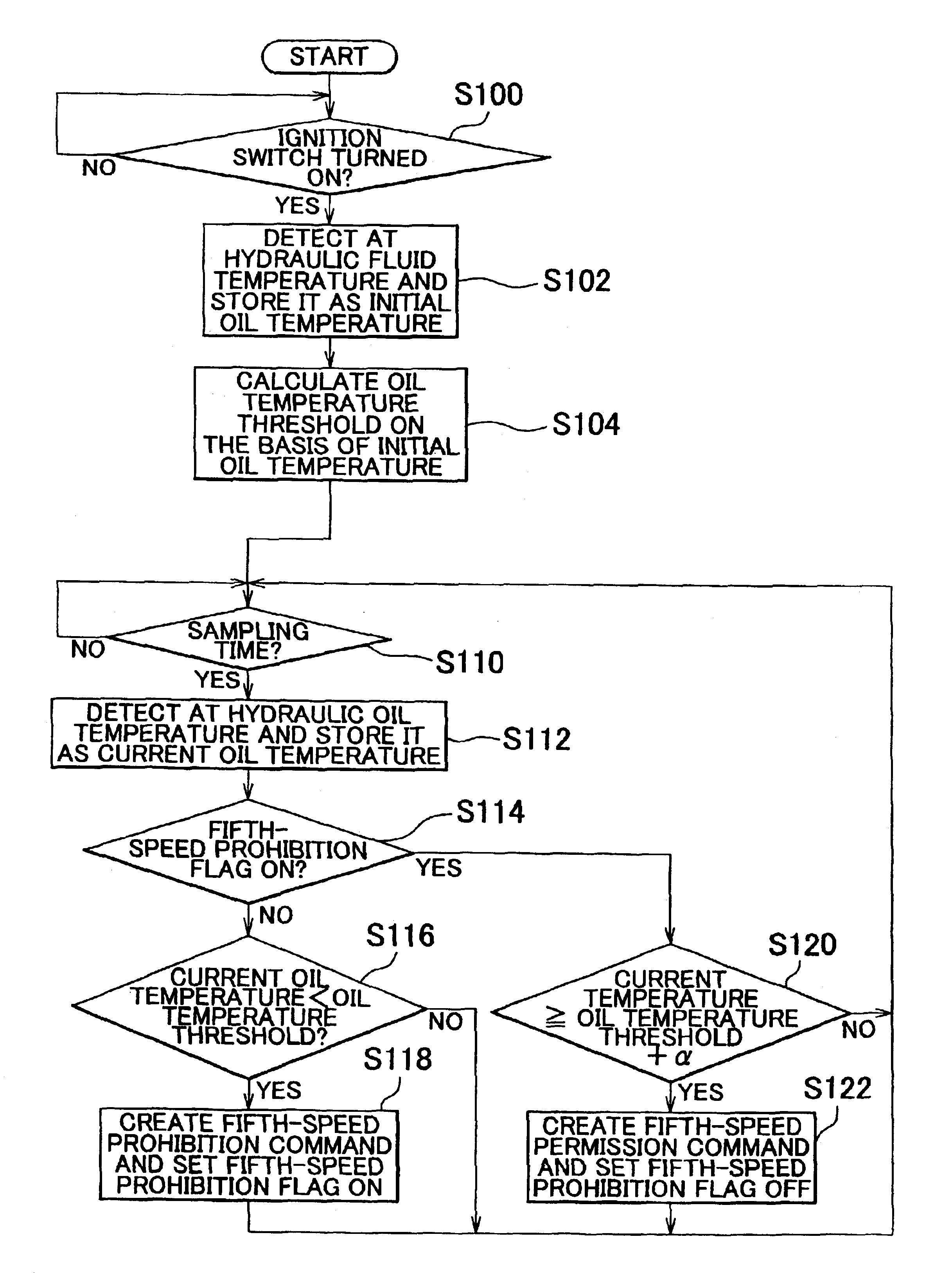
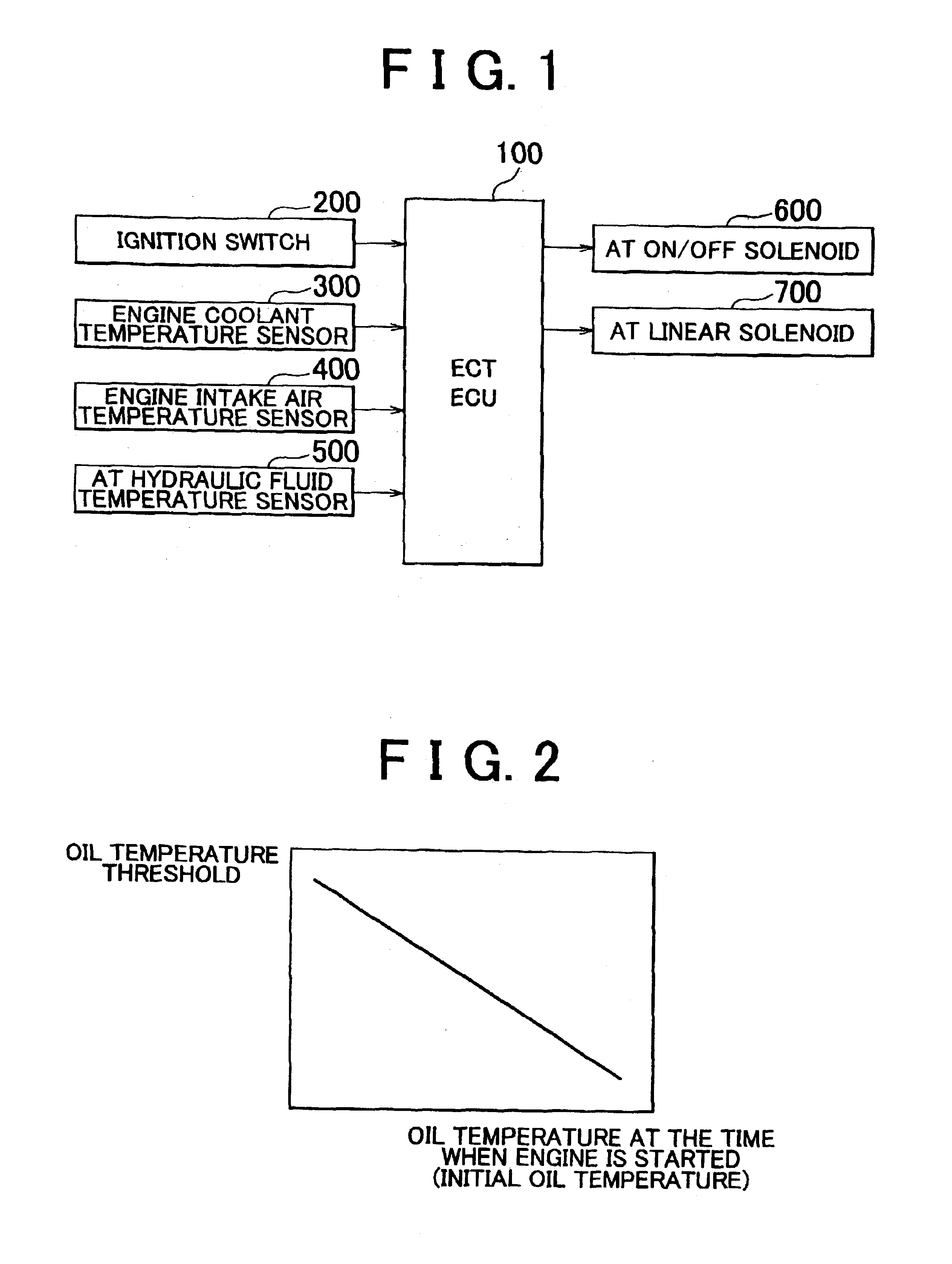
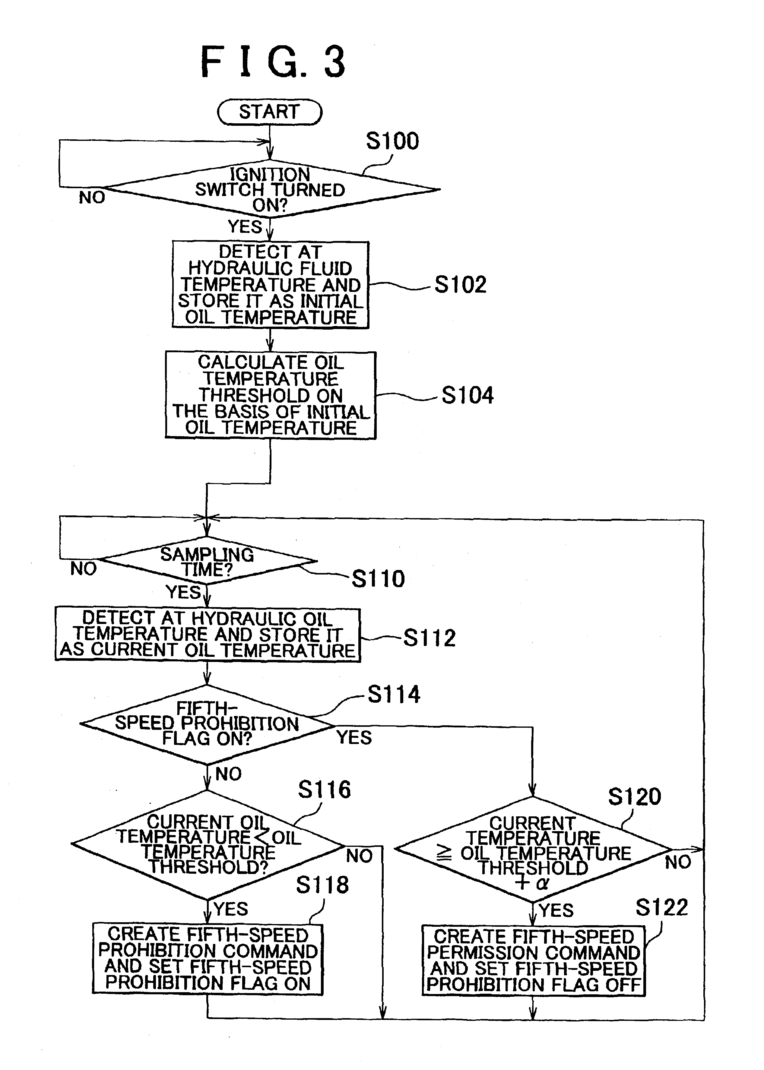
[0035]FIG. 1 is a control block diagram of an automatic gear-shift system including an ECT-ECU (Electronically Controlled Automatic Transmission—Electronic Control Unit) 100 that realizes a control device for an automatic transmission in accordance with the first embodiment. As shown in FIG. 1, the ECT-ECU 100 of this system is a controller for controlling the automatic transmission. The ECT-ECU 100 includes a memory that stores programs and various data, a CPU (Central Processing Unit) that executes the programs stored in the memory, a clock that generates a fundamental motion frequency, and the like. The ECT-ECU 100 corresponds to a calculating portion as calculating means, a storing portion as storing means, a control portion as control means, and a measuring portion as measuring means.
[0036]Input signal lines extending from an ignition switch 200, an engine coolant temperature sensor 300, an engine intake air temperature sensor 400, and an AT hydraulic fluid te...
second embodiment
[Second Embodiment]
[0058]The ECT-ECU 100 in accordance with the second embodiment detects a time when the engine is started on the basis of a signal input from the ignition switch 200, detects an engine coolant temperature at that moment, and stores it in the memory as an initial coolant temperature. The ECT-ECU 100 calculates an oil temperature threshold on the basis of the initial coolant temperature and a relationship that is stored in the memory and that indicates how the oil temperature threshold is related to initial coolant temperature. As shown in FIG. 4, according to the relationship that is stored in the memory and that indicates how oil temperature threshold is related to the initial coolant temperature, the oil temperature threshold rises in proportion to a fall in the initial coolant temperature and falls in proportion to a rise in the initial coolant temperature. Although the initial coolant temperature and oil temperature threshold establish a linear relationship in F...
third embodiment
[Third Embodiment]
[0067]The ECT-ECU 100 in accordance with the third embodiment detects start of the engine on the basis of a signal input from the ignition switch 200, detects a temperature of intake air introduced into the engine at that moment, and stores it in the memory as an initial intake air temperature. The ECT-ECU 100 calculates an oil temperature threshold on the basis of the initial intake air temperature and a relationship that is stored in the memory and that indicates how the oil temperature threshold is related to the initial intake air temperature. As shown in FIG. 6, according to the relationship that is stored in the memory and that indicates how the oil temperature threshold is related to the initial intake air temperature, the oil temperature threshold rises in proportion to a fall in the initial intake air temperature and falls in proportion to a rise in the initial intake air temperature. Although the initial intake air temperature and oil temperature threshol...
PUM
 Abstract
Description
Claims
Application Information