Vehicle suspension system

a suspension system and vehicle technology, applied in the direction of resilient suspensions, interconnection systems, vehicle components, etc., can solve the problems of insufficient ride comfort, inability to provide sufficient ride comfort, and inability to provide a balanced load support and acceptable ride comfor

Inactive Publication Date: 2005-07-12
THE HOLLAND GROUP
View PDF9 Cites 3 Cited by
  • Summary
  • Abstract
  • Description
  • Claims
  • Application Information

AI Technical Summary

Benefits of technology

[0006]The present inventive vehicle suspension system provides a tandem axle walking beam suspension with a single point air isolation, thereby allowing simultaneous optimization of longitudinal roll stability and ride comfort.

Problems solved by technology

Heretofore, these systems have proven inadequate to simultaneously provide acceptable load support and acceptable ride comfort.
Specifically, the systems utilizing leaf springs provide adequate load support, however fail to provide sufficient ride comfort.
The result is a fixed rate suspension system, thereby creating a relatively rougher ride as the load on the frame is reduced.
On the other hand, systems utilizing air cylinders provide adequate ride comfort; however, fail to provide sufficient longitudinal roll stability.
However, these systems have failed to provide adequate longitudinal roll stability.

Method used


Image

  • Vehicle suspension system
  • Vehicle suspension system
  • Vehicle suspension system

Examples


Embodiment Construction

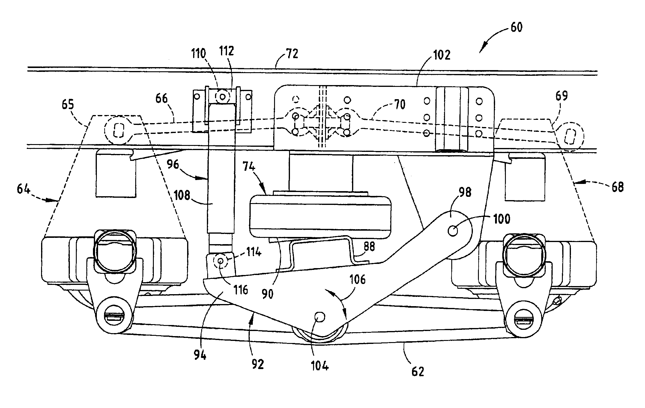
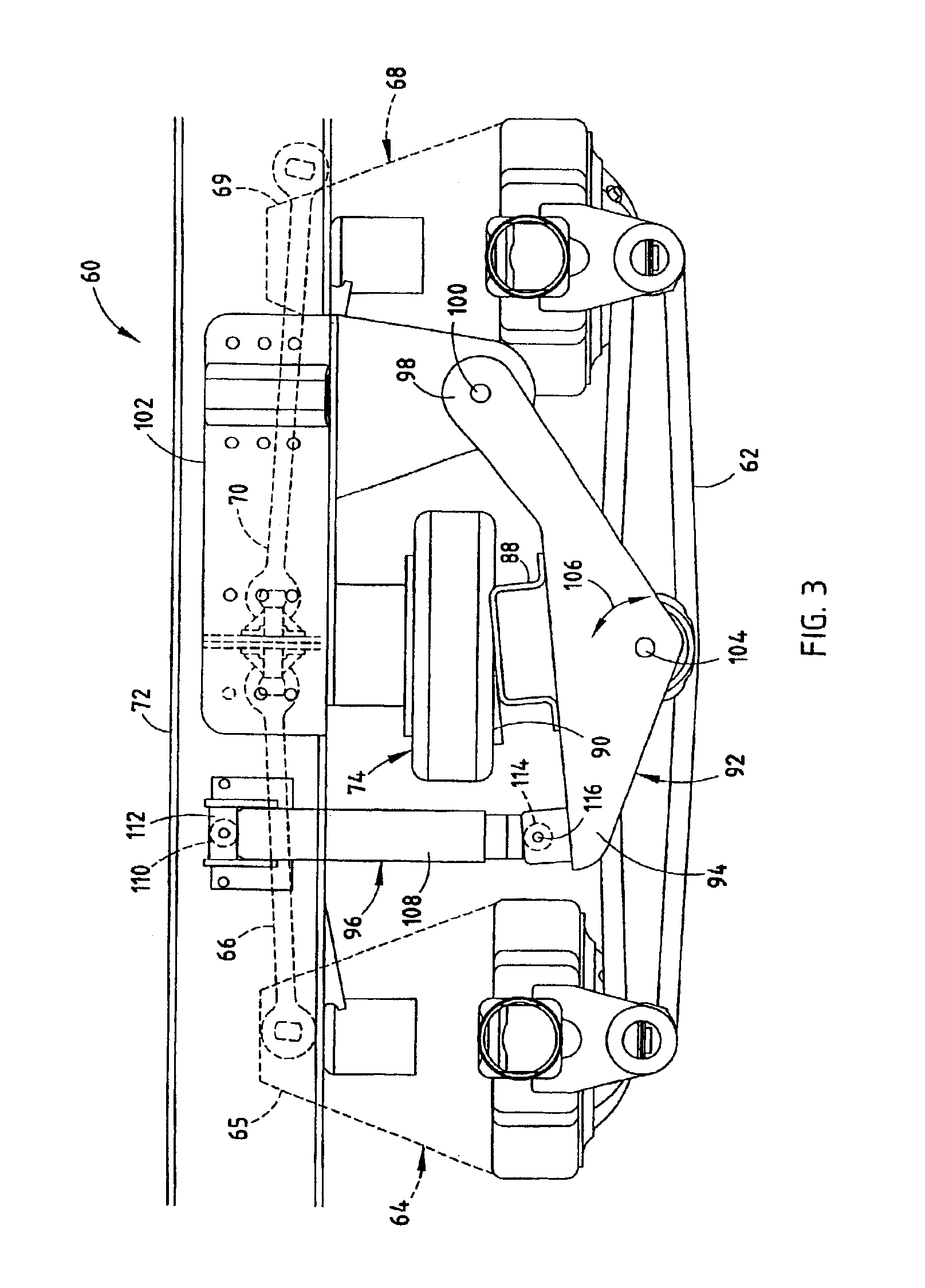
[0018]For purposes of description herein, the terms “upper,”“lower,”“right,”“left,”“rear,”“front,”“vertical,”“horizontal,” and derivatives thereof shall relate to the invention as oriented in FIG. 3. However, it is to be understood that the invention may assume various alternative orientations and step sequences, except where expressly specified to the contrary. It is also to be understood that the specific devices and processes illustrated in the attached drawings, and described in the following specification are exemplary embodiments of the inventive concepts defined in the appended claims. Hence, specific dimensions and other physical characteristics relating to the embodiments disclosed herein are not to be considered as limiting, unless the claims expressly state otherwise.

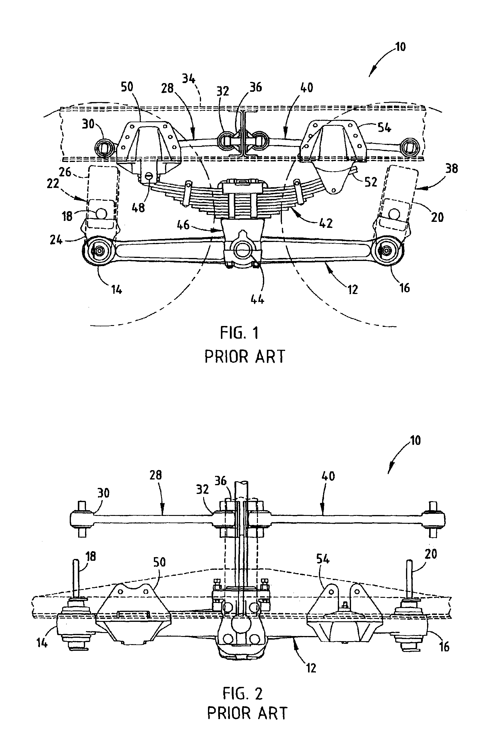
[0019]A prior art vehicle suspension assembly 10 is illustrated in FIGS. 1 and 2. As is consistent throughout this application, only the left side of the suspension assembly 10 is described, as the left and r...


PUM


Abstract

A vehicle suspension system includes a pair of equalizing beams, two pairs of axle housings each having a lower portion connected to opposite ends of the equalizing beams, two pairs of linkage arms operably connected to an upper portion of each of the axle housings and with a vehicle frame, and a pair of air cylinders operably connected to the equalizing beams at a point located between the ends of the beams and with the vehicle frame. The system further includes a torsional beam extending between the first and second air cylinders, wherein the torsional beam provides the operable connection between the first cylinder and the point of the first equalizing beam located between the ends of the first equalizing beam, and the operable connection between the second cylinder and the point of the second equalizing beam located between the ends of the second equalizing beam.

Description

CROSS-REFERENCE TO RELATED APPLICATION[0001]This application claims the benefit of U.S. Provisional Application No. 60 / 394,823, filed Jul. 10, 2002, entitled VEHICLE SUSPENSION SYSTEM, which is hereby incorporated herein by reference in its entiretyBACKGROUND OF THE INVENTION[0002]The present invention relates to a vehicle suspension system, and in particular to a heavy duty, walking beam-type suspension system.[0003]A variety of vehicle suspension units have been developed for vehicles that include two or more pairs of drive wheels. These suspension systems include single, tandem and tridem suspension systems, as well as equalizing or walking beam-type systems. Walking beam type systems, as described in more detail below, typically include a plurality of linkage arms cooperating to form a parallelogram, wherein one of the members, an equalizing beam, pivotally connects a pair of associated axles. A suspension unit is then supported between the associated frame of the supported vehi...

Claims


Application Information

Patent Timeline
Patent Type & Authority Patents(United States)
IPC IPC(8): B60G5/00B60G5/02
CPCB60G5/02
Inventor MCKENZIE, THOMAS A.HICKS, WILLIAM J.
Owner THE HOLLAND GROUP
Why Eureka
Try Eureka