Device for grasping load structure

a load structure and device technology, applied in the direction of lifting devices, load-engaging elements, hoisting equipment, etc., can solve the problems of manual force in many tasks in setting the load structure, the risk of serious injury of workers manually moving the load structure, and the difficulty in accurately positioning the load structure as it is being lowered. , to achieve the effect of simple design, low cost and low cos

Inactive Publication Date: 2007-10-25
HERFORD SHANNON M
View PDF22 Cites 1 Cited by
  • Summary
  • Abstract
  • Description
  • Claims
  • Application Information

AI Technical Summary

Benefits of technology

[0006] The present invention relates to a device for grasping load structures and more particularly, to a device for grasping utility sections such as the castings and riser rings used in municipal drains while they are being lifted, moved or lowered. The claimed grasping device is durable and efficient to use, having a simple design that minimizes the number of members and joints. The grasping device is adapted to be coupled to lifting equipment, such as an overhead crane or the like. Furthermore, the grasping device enables the load structure to be set by a single worker and minimizes the number of tasks requiring manual force by that worker.

Problems solved by technology

There are many drawbacks associated with using chains and similar grasping devices to lift or move drain sections such as castings and riser rings.
While the lifting equipment provides the lifting force, many of the tasks in setting the load structure require manual force.
For example, in using chains, the load structure may tilt off the level plane making it difficult to accurately position the load structure as it is being lowered.
This is also dangerous because the worker who manually moves the load structure risks serious injury if the load structure become unstable and falls.
Therefore, the problems associated with using traditional grasping devices, such as chains, can lead to fatigue and injury and often requires the use of two or more workers.

Method used


Image

  • Device for grasping load structure
  • Device for grasping load structure
  • Device for grasping load structure

Examples


Embodiment Construction

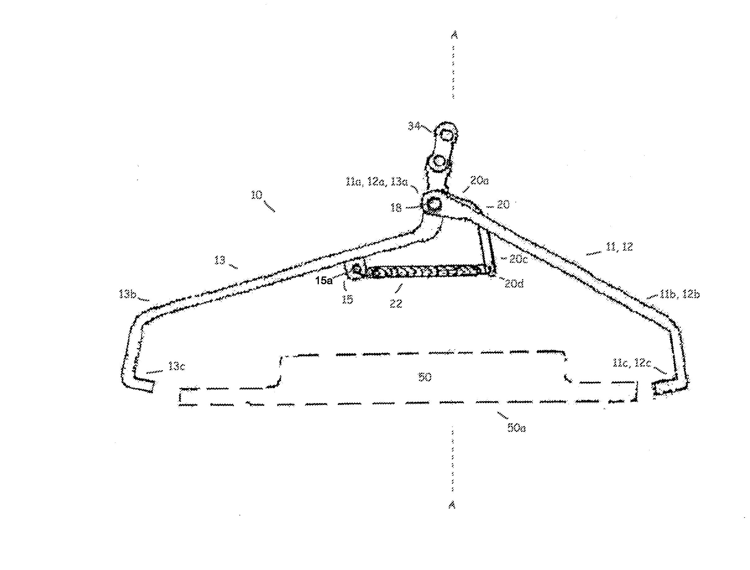
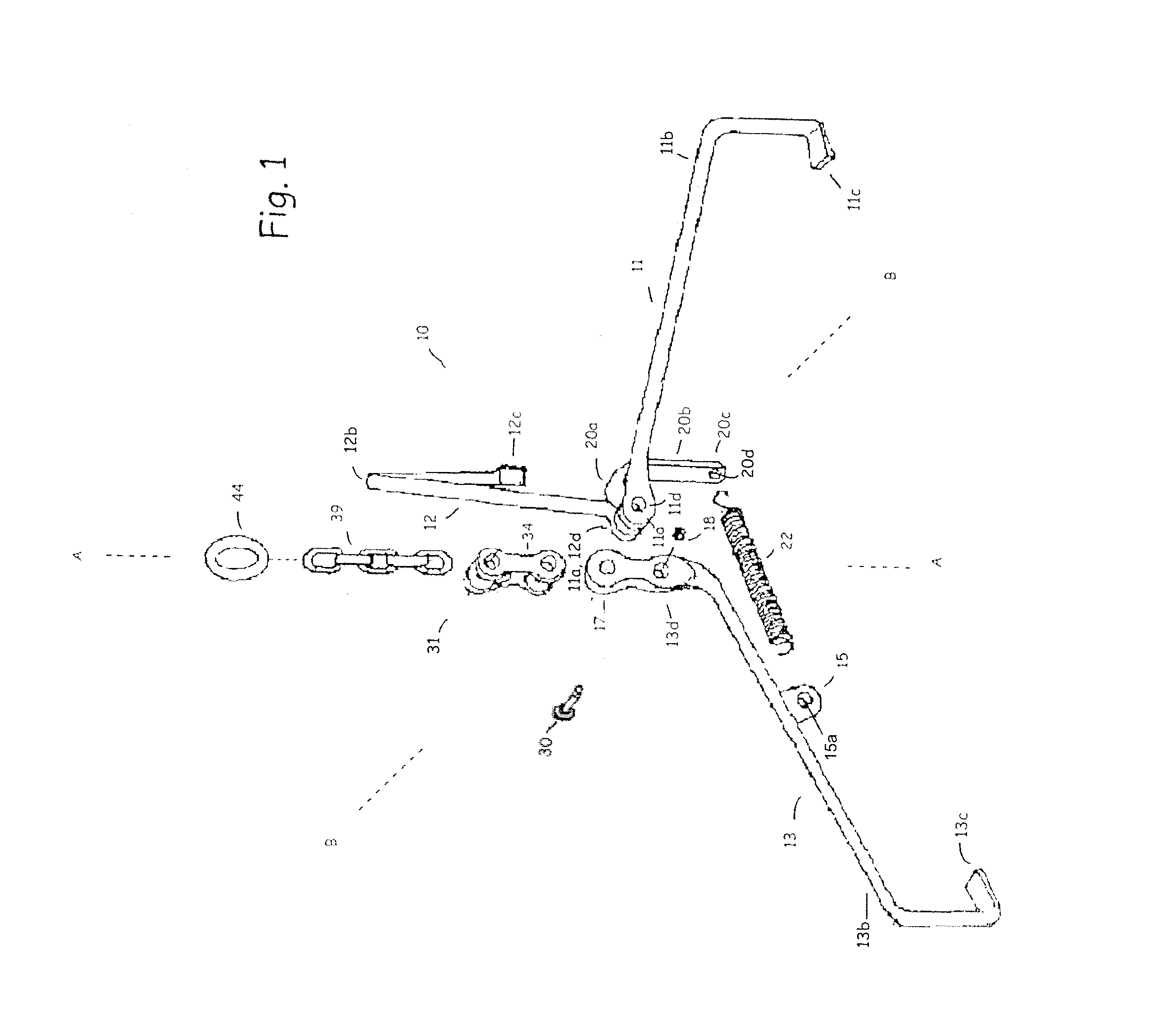
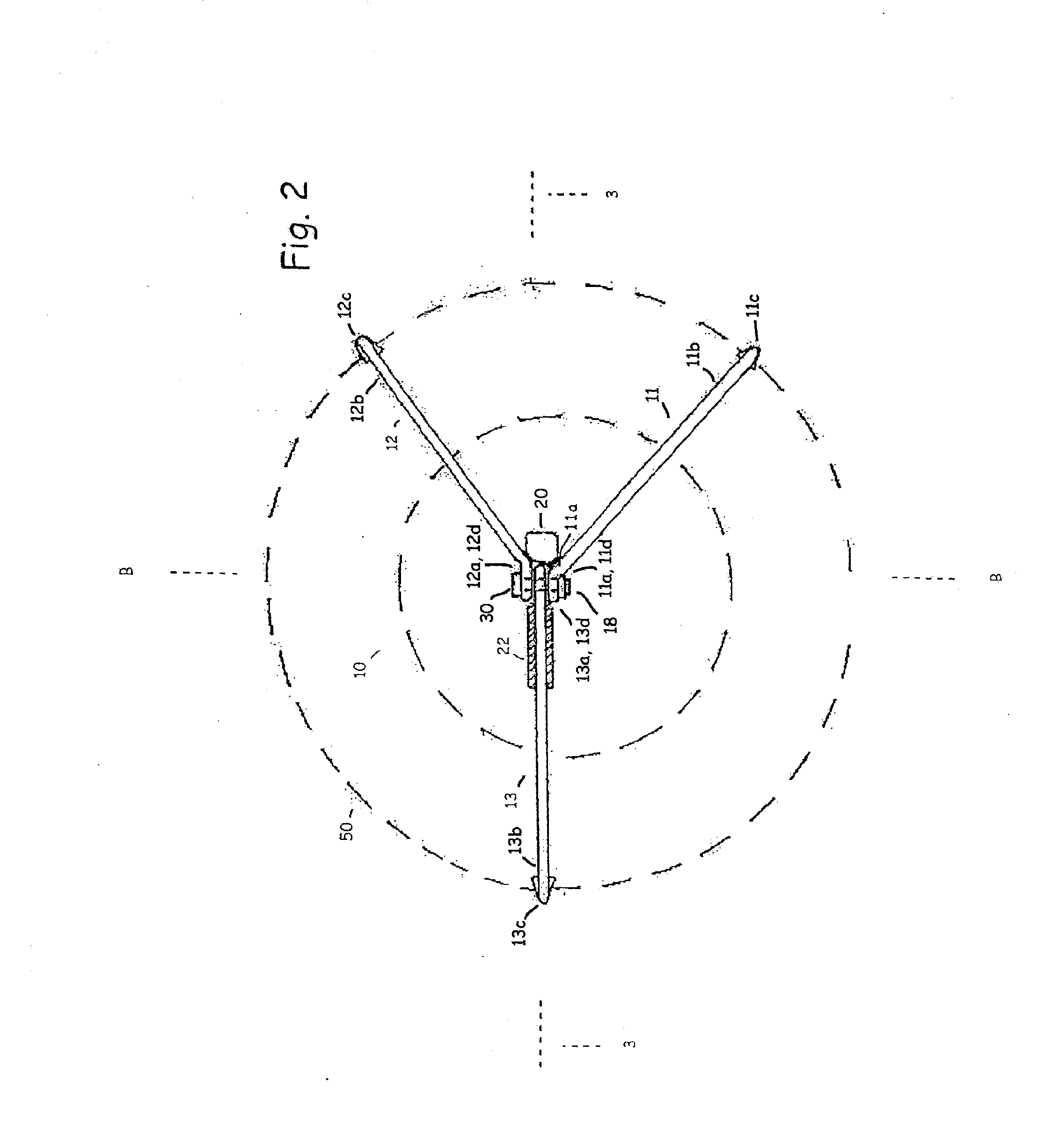
[0014] Referring to FIG. 1, an embodiment of the grasping device of the present application generally referred to as numeral 10, is shown. The embodiment includes a first leg 11, a second leg 12 and a third leg 13. Each leg 11, 12, 13 respectively includes arms 11b, 12b, 13b with respective pivot portions 11a, 12a 13a at first ends thereof. The opposing ends of the arms 11b, 12b, 13b respectively include lift portions 11c, 12c, 13c, which may be in the form of depending feet that are substantially parallel to vertical axis A-A and adapted to engage a bottomside of a load structure 50. It will be appreciated that while the present invention has been described with only three legs, alternate embodiments having four or more legs are possible without departing from the true scope and spirit of the present application. The legs 11, 12, 13 are preferably substantially rigid and of one-piece construction, fabricated from either round or square steel stock, but may also be forged or cast in...


PUM


Abstract

A device for grasping a load structure while it is being lifted, moved or lowered, comprising first, second and third legs, each extending radially outwardly from a vertical axis and adapted to pivotally engage a pivot member. The first, second and third legs are each adapted to pivot between an engaged position and a released position, and an urging member urges the legs toward the engaged position.

Description

BACKGROUND OF THE INVENTION [0001] The present invention relates to a device for grasping load structures and more particularly, to a device for grasping utility sections such as the castings and riser rings used in municipal drains while they are being lifted, moved or lowered. [0002] Many construction projects involving municipal storm and sewer drains require the setting of iron castings above manholes. In setting a casting, workers must ensure that the casting is properly graded with the ground surface. As such, workers adjust the elevation of the casting by placing a concrete riser ring of appropriate height, typically between four and twelve inches, in order to grade the casting. [0003] Because riser rings and castings generally weigh between 100 and 500 pounds, it is desirable to lift such load structures using a lifting device such as an overhead crane or the like. Traditionally, workers would use chains to rig the load structure to the lifting device. [0004] There are many ...

Claims


Application Information

Patent Timeline
Patent Type & Authority Applications(United States)
IPC IPC(8): B66C1/42
CPCB66F19/005
Inventor HERFORD, EDWIN DENNIS
Owner HERFORD SHANNON M
Why Eureka
Try Eureka