
Devices and methods for fluid mixing

a fluid mixing and fluid technology, applied in the field of fluid mixing devices and methods, can solve the problems of complex construction of valve technologies, difficulty in adapting valve structures to microfluidic devices, and difficulty in producing such devices

Inactive Publication Date: 2005-07-12
AGILENT TECH INC
View PDF31 Cites 122 Cited by
  • Summary
  • Abstract
  • Description
  • Claims
  • Application Information

AI Technical Summary

Benefits of technology

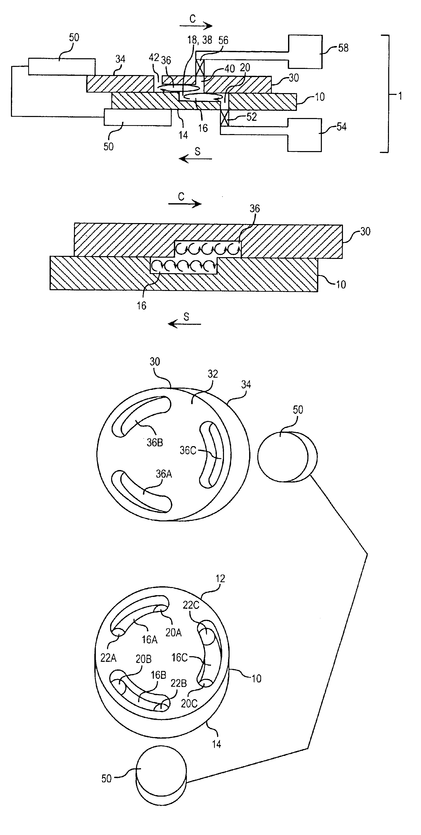
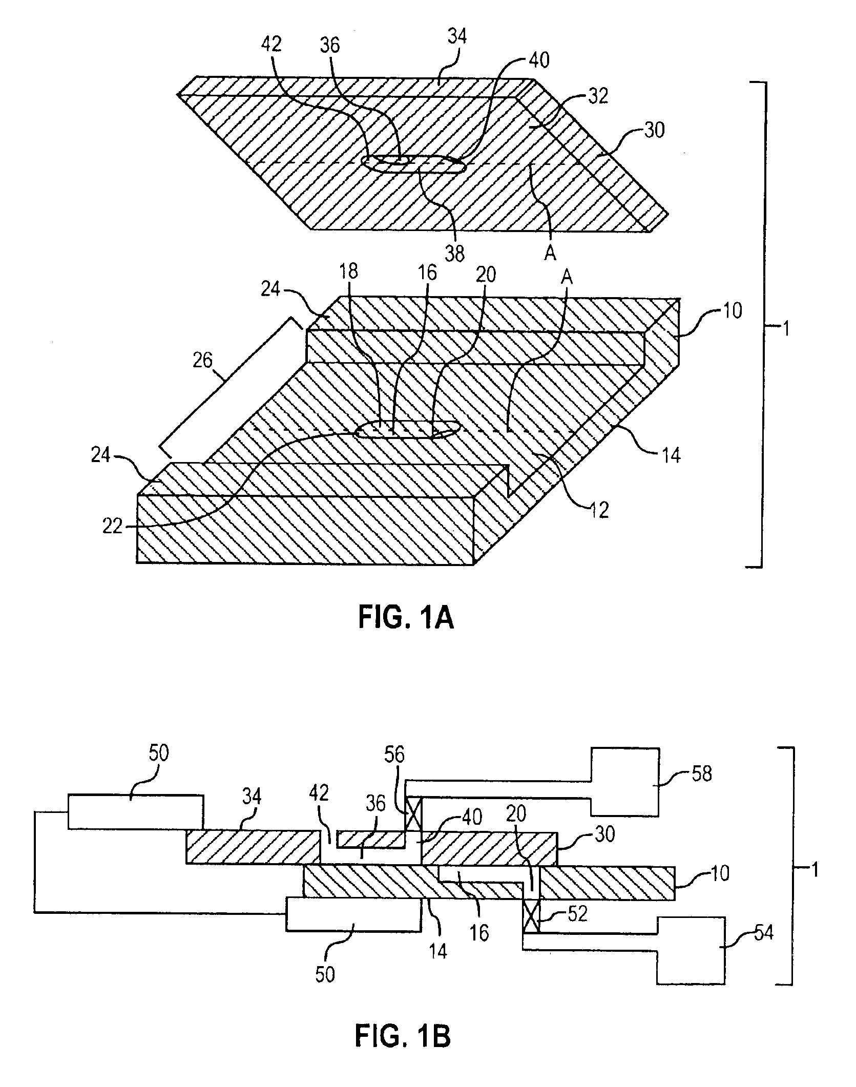
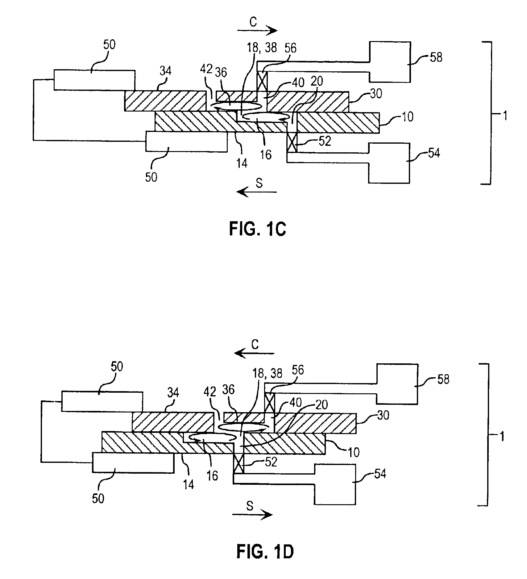
The invention is a device for mixing fluids that includes a substrate and a cover plate with matching mixing features that induce fluid mixing when the surfaces of the substrate and cover plate are in relative sliding motion. The device can be used in microfluidic applications and the mixing features can have a volume of at least about 1 pL. The method involves filling the mixing features with fluids and producing relative sliding motion between the substrate and cover plate surfaces. The technical effects of the invention include efficient mixing of fluids with low volumes and the ability to induce mixing through relatively small openings.

Problems solved by technology

Nevertheless, the production of such devices presents various challenges.
In particular, the implementation of fluid flow control and fluid mixing in microdevices presents unique challenges.
With respect to fluid flow control, for example, conventional wisdom dictates that valve structures, which control flow of fluids in bulk, are not easily adaptable for use in microfluidic devices due to the predominance of surface effects.
Many of these valve technologies, however, are complex in construction and are incapable of the fast response times required in certain biomolecule analysis applications due to an excess of “dead space,” i.e., unused and unnecessary space within the microdevice.
The mixing techniques discussed above suffer from a number of drawbacks.
Like the conventional valve technology described above, the active mixing technologies are usually complex in construction.
In addition, both active and passive mixing technologies ordinarily require dedicated regions within a microdevice, which tends to increase the size and complexity of the microdevice.

Method used


Image

  • Devices and methods for fluid mixing
  • Devices and methods for fluid mixing
  • Devices and methods for fluid mixing

Examples


Embodiment Construction

[0021]Before the invention is described in detail, it is to be understood that, unless otherwise indicated, this invention is not limited to particular materials, components or manufacturing processes, as such may vary. It is also to be understood that the terminology used herein is for purposes of describing particular embodiments only, and is not intended to be limiting.

[0022]As used in the specification and the appended claims, the singular forms “a,”“an” and “the” include plural referents unless the context clearly dictates otherwise. Thus, for example, reference to “a mixing feature” includes a single mixing feature as well as a plurality of mixing features, reference to “an inlet” includes a single inlet as well as multiple inlets, reference to “a fluid” includes a single fluid as well as mixture of fluids, and the like.

[0023]In this specification and in the claims that follow, reference will be made to a number of terms that shall be defined to have the following meanings, un...


PUM

PropertyMeasurementUnit
frequencyaaaaaaaaaa
frequencyaaaaaaaaaa
frequencyaaaaaaaaaa

Abstract

A device for mixing fluids is provided. The device is comprised of a substrate containing a first mixing feature that terminates at a first opening located on a surface of the substrate and a cover plate containing a second mixing feature that terminates at a second opening located on a surface of the cover plate. Also provided is a means for producing relative sliding motion between the cover plate and substrate surfaces. The substrate and cover plate surfaces are maintained in fluid-tight contact with each other such that relative sliding motion between the first and second mixing features induces fluid mixing through the first and second openings when fluid is present in the mixing features. Also provided is a method for mixing fluids. The device and method are particularly suited for microfluidic applications.

Description

TECHNICAL FIELD[0001]The present invention generally relates to devices and methods for mixing fluids. More specifically, the invention relates to devices and methods that use relative sliding motion between mixing features of a cover plate and a substrate to mix fluids within the mixing features. The invention is particularly suited for microfluidic applications and for mixing small volumes of fluids.BACKGROUND[0002]Microfluidic devices (microdevices) hold great promise for many fields of use, including chemical analysis or clinical diagnostics. The small size of microdevices allows for the analysis of minute quantities of fluids or samples, which is an important advantage when the fluids or samples are expensive or difficult to obtain. To enhance the functionality of sample analysis devices, it has been proposed that preparation, separation and detection compartments be integrated on such devices. Microfluidic technologies are generally described, for example, in U.S. Pat. Nos. 5,...

Claims


Application Information

Patent Timeline
Patent Type & Authority Patents(United States)
IPC IPC(8): B01F13/00B01F11/00
CPCB01F11/0042B01F11/0048B01F13/0059B01F2215/0431B01F2215/0454Y10S366/03B01F31/311B01F31/29B01F33/30
Inventor VAN DE GOOR, TOMBRENNEN, REID A.
Owner AGILENT TECH INC
Learn More