Array socket with a dedicated power/ground conductor bus

a power/ground conductor and array socket technology, applied in the direction of printed circuit aspects, high current circuit adaptation, electrical apparatus construction details, etc., can solve the problems of reducing power delivery capacity, increasing power and i/o paths, and difficult to find a workable routing schem

Inactive Publication Date: 2005-07-12
INTEL CORP
View PDF7 Cites 64 Cited by
  • Summary
  • Abstract
  • Description
  • Claims
  • Application Information

AI Technical Summary

Problems solved by technology

Thus, in complex microchips, finding a workable routing scheme becomes a complex task.
Furthermore, as microchips become faster, more powerful, and generally speaking more complicated, they demand increasing amounts of power and I / O paths.
The current trend of tighter I / O package pitches P is cornering chip designers into a two-fold problem-reduced power delivery capacity and increased power supply demand.

Method used


Image

  • Array socket with a dedicated power/ground conductor bus
  • Array socket with a dedicated power/ground conductor bus
  • Array socket with a dedicated power/ground conductor bus

Examples


Embodiment Construction

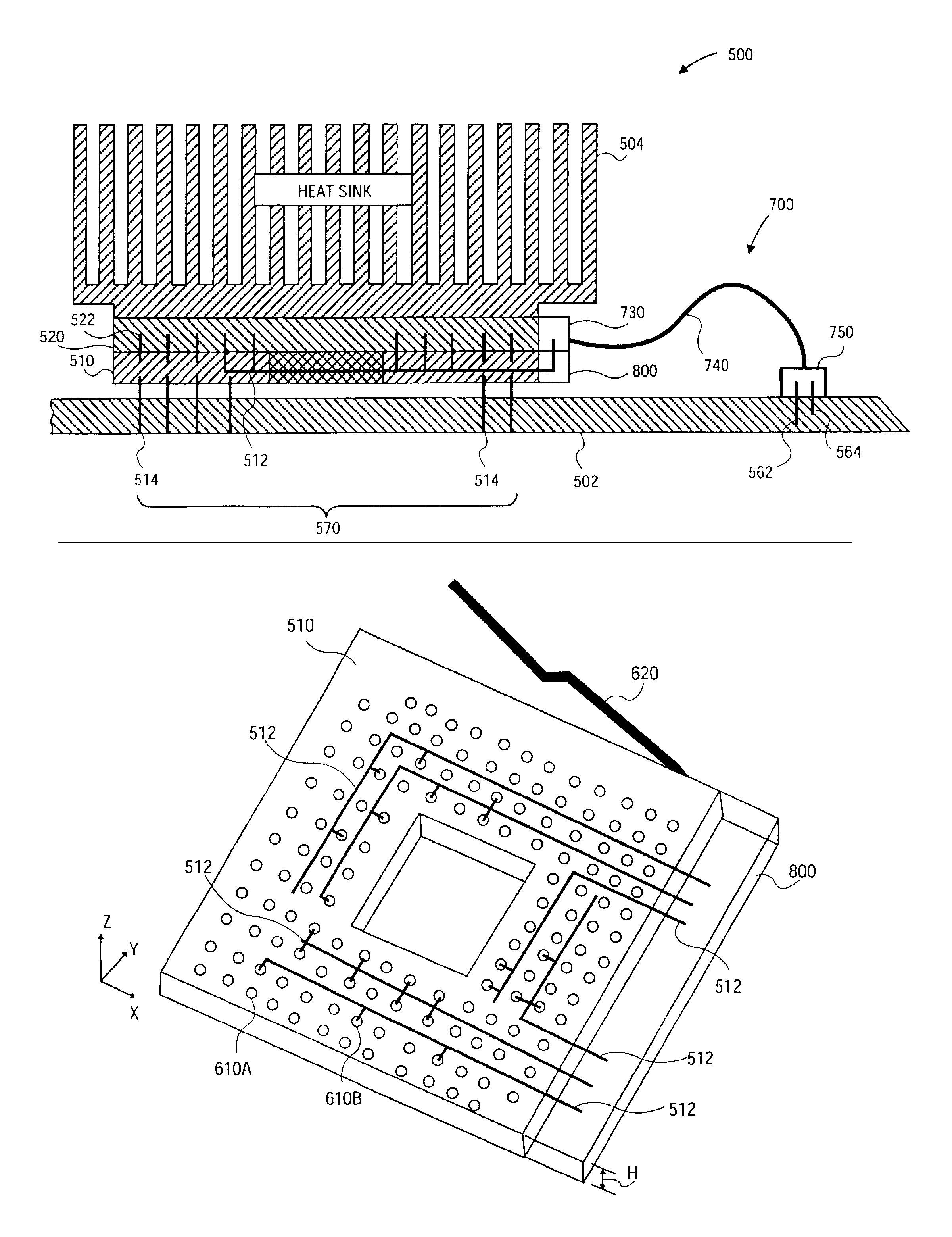
[0019]Embodiments of a method and apparatus for implementing an array socket having a conductor bus are described herein. In the following description numerous specific details are set forth to provide a thorough understanding of embodiments of the invention. One skilled in the relevant art will recognize, however, that the invention can be practiced without one or more of the specific details, or with other methods, components, materials, etc. In other instances, well-known structures, materials, or operations are not shown or described in detail to avoid obscuring aspects of the invention.

[0020]Reference throughout this specification to “one embodiment” or “an embodiment” means that a particular feature, structure, or characteristic described in connection with the embodiment is included in at least one embodiment of the present invention. Thus, the appearances of the phrases “in one embodiment” or “in an embodiment” in various places throughout this specification are not necessar...


PUM


Abstract

An apparatus for receiving a microchip and having a conductor buses therein. A top surface of the apparatus receives the microchip while the bottom surface is to mount to a circuit board. A plurality of pin receptacles pass through the top surface to receive a corresponding plurality of microchip pins of the microchip. The conductor bus resides at least in part between the top surface and the bottom surface and is electrically coupled to a first plurality of the plurality of the pin receptacles.

Description

TECHNICAL FIELD[0001]This disclosure relates generally to array sockets for coupling to microchips and in particular but not exclusively, relates to providing a dedicated power / ground conductor bus within the array socket.BACKGROUND INFORMATION[0002]Array sockets are widely used to seat a microchip on a circuit board so that the microchip may be replaced or upgraded to improve performance at a later date. Typical microchips include, but are not limited to, memory modules, microprocessors, and BIOS chips.[0003]FIG. 1 is a cross-sectional view of an exemplary array socket system 100 including a microchip 120 having microchip pins 125 seated in corresponding pin receptacles (not shown) of an array socket 110. Array socket 110 includes a plurality of socket pins 145 that are electrically coupled within array socket 110 to the corresponding pin receptacles. Socket pins 145 are electrically connected to conductor traces 230 (FIG. 2) such that signals and / or power may be delivered to / from ...

Claims


Application Information

Patent Timeline
Patent Type & Authority Patents(United States)
IPC IPC(8): H05K1/14H05K1/02H05K7/10
CPCH05K1/0263H05K1/147H05K7/1092H05K1/141H05K2201/10189H05K2201/1053H05K2201/10704
Inventor ALGER, WILLIAM O.LONG, GARY B.BRIST, GARY A.MEJIA, CARLOS
Owner INTEL CORP
Why Eureka
Try Eureka