Canopy air delivery system

a canopy and air delivery technology, applied in ventilation systems, heating types, separation processes, etc., can solve the problems of difficult sealing and sealing when entering and leaving the enclosure, difficult to make much difference in the air in the room in this way, and high building and operation costs of the room

Inactive Publication Date: 2005-07-12
NAT BUSINESS CONSULTANTS
View PDF16 Cites 32 Cited by
  • Summary
  • Abstract
  • Description
  • Claims
  • Application Information

AI Technical Summary

Benefits of technology

[0013]The air diffuser comprises a housing having an air impervious rear wall, air impervious side walls, and a perforated front wall which directs air from the diffuser into the area adjacent the front wall. The housing forms a plenum for pressurized air to be directed through the perforations in the front wall of the housing. A filter bag connected to a source of pressurized air is positioned in the plenum to filter pressurized air supplied to the plenum and distribute the filtered pressurized air in the plenum. The filter bag is positioned in the housing so as to minimize or limit contact of the bag with the perforated front wall. This prevents the filter bag from blocking the perforations in the front wall and ensures a more even flow of filtered air through the front wall. The bag may be positioned in the housing by securing the corners of the bag to the housing or by various other means such as a screen located in the housing spaced from the perforated front wall. The rear wall of the housing is preferably channeled so that air can flow from the bag into such channels and flow along the rear wall and around the edges of the bag into the plenum adjacent the front wall to provide more air capacity to the diffuser and more even distribution of air in the plenum.

Problems solved by technology

However, such rooms are expensive to build and operate so are used only when absolutely necessary.
It is difficult to make much difference in the room air in this way, however, because only a small portion of the air in the room is passed through the filter at any one time and the filtered air from the filter is immediately mixed with room air as it is discharged from the filter prior to reaching the person or localized site needing the filtered air.
However, a person is isolated in the enclosure and it is difficult to open and close the seals when entering and leaving the enclosure.
However, the filtered air is mixed with room air in the work station so the station air is a mixture of filtered and unfiltered air.

Method used


Image

  • Canopy air delivery system
  • Canopy air delivery system
  • Canopy air delivery system

Examples


Embodiment Construction

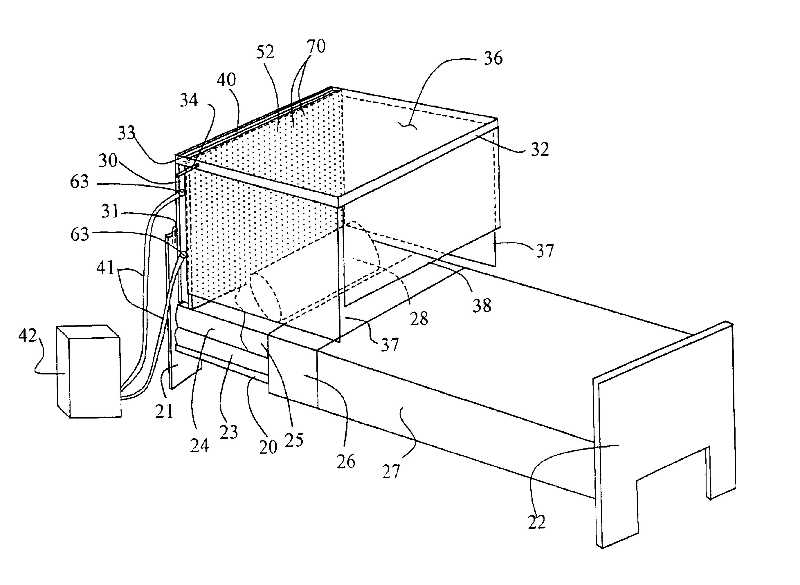
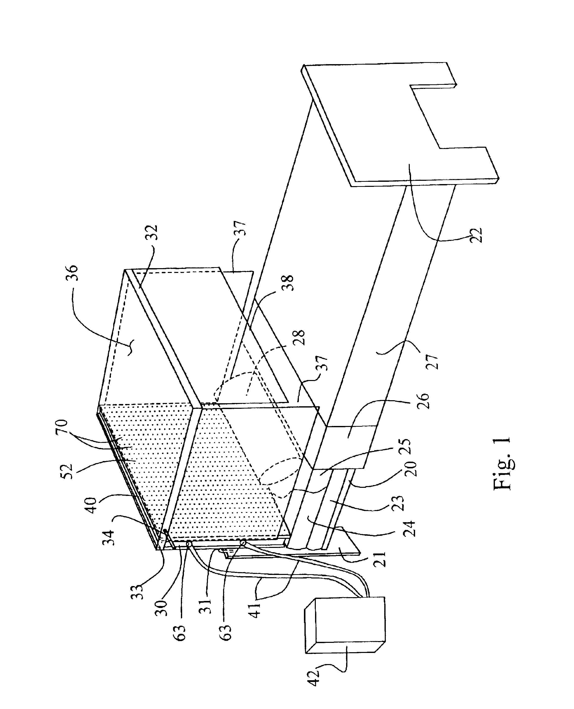
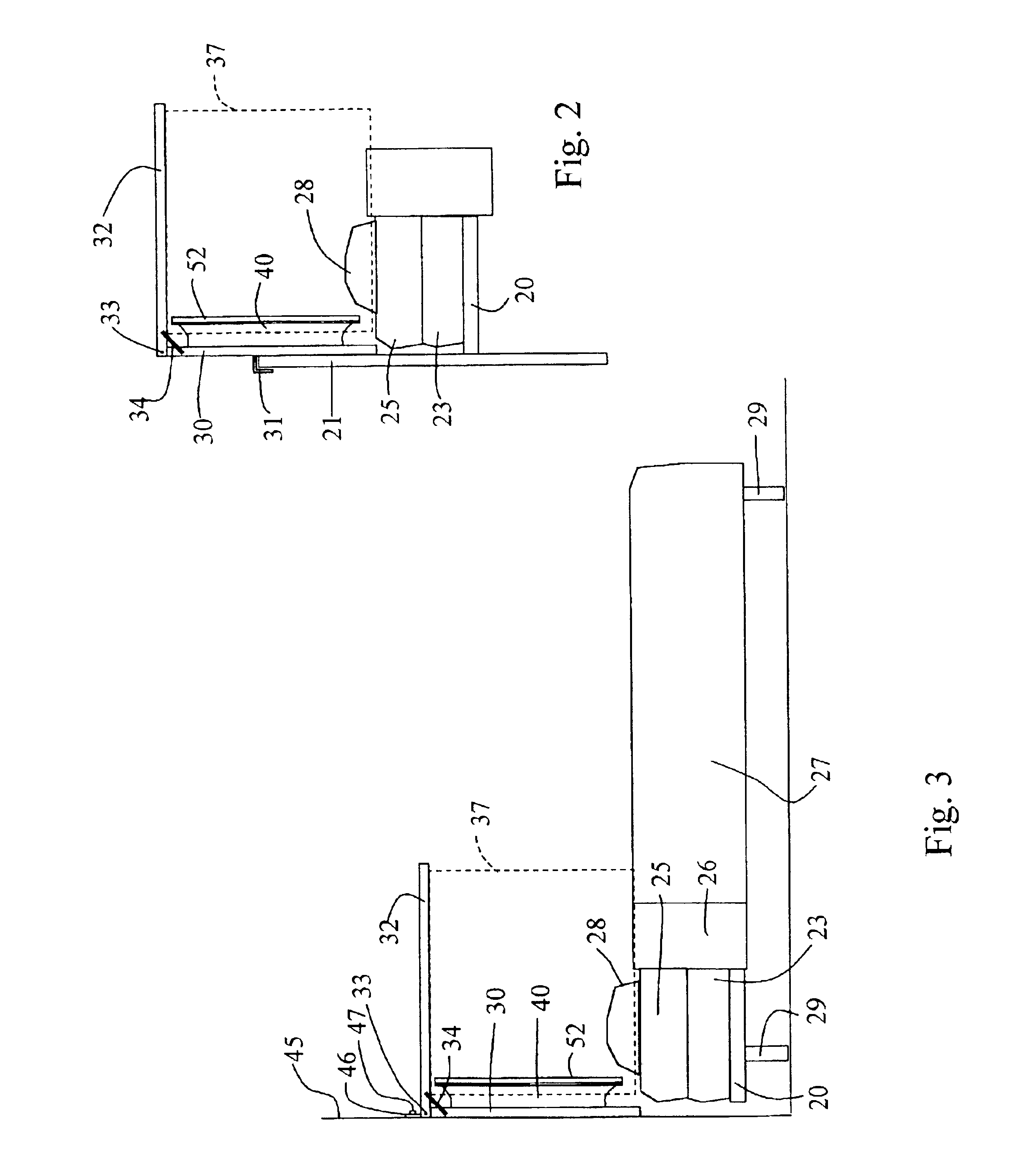
[0023]FIGS. 1 and 2 show an embodiment of the area air delivery system of the invention as applied to a bed. The bed could be a hospital bed or could be a bed in a home or in a hotel. It also could be any size bed from a hospital size bed to a king size bed. As shown, the bed has a supporting frame 20 with a supporting headboard 21 and supporting footboard 22, which form supporting legs for the bed. This is a common bed configuration. Other bed configurations can be used, such as the other common configuration as shown in FIG. 3 where supporting legs 29 extend from the frame 20 with no headboard or footboard. A box spring 23 and mattress 24 rest on frame 20 and are shown with standard bedding sheets 25 and 26, blanket 27, and pillow 28.

[0024]In the embodiment shown in FIGS. 1 and 2 with a headboard, a canopy frame vertical portion 30 is attached to the headboard 21 such as with hooks 31 which fit over the top of the headboard. However, any type of attachment could be used. A canopy ...


PUM

PropertyMeasurementUnit
distanceaaaaaaaaaa
porosityaaaaaaaaaa
areaaaaaaaaaaa

Abstract

An area air delivery system for delivery of filtered air to an area occupiable by a user who can enter and leave the area, such as the head end of a bed, includes a canopy for at least partially surrounding the area to which air is to be supplied and defining the area which a user can enter and leave. An air diffuser positioned in the canopy includes a housing having an air impervious rear wall, air impervious side walls, and a perforated front wall forming a plenum in which a filter bag resides. The plenum is connected to a source of pressurized, preferably prefiltered, air so that pressurized air is supplied to the interior of the filter bag to diffuse through the filter bag into the plenum. Perforations in a predetermined area of the perforated front wall of the housing allow air to flow through the perforations and provide a substantially even flow of air from the perforated front wall of the diffuser into the canopy.

Description

RELATED APPLICATION[0001]This application claims the benefit of provisional Application Ser. No. 60 / 304,377, filed Jul. 10, 2001, and entitled “Canopy Air Delivery System.”BACKGROUND OF THE INVENTION[0002]1. Field[0003]The invention is in the field of providing filtered air environments, particularly of providing filtered air to localized areas occupied by persons needing or desiring such environments.[0004]2. State of the Art[0005]There are various situation where an environment of filtered air is desirable. In some manufacturing processes, such as semiconductor manufacture, clean air is required. Such manufacturing usually takes place in clean rooms, entire rooms provided with special high capacity filtering systems that circulate clean air into and through the rooms. However, such rooms are expensive to build and operate so are used only when absolutely necessary. U.S. Pat. No. 5,195,922 discloses a modular system for providing clean room environments in small areas for particula...

Claims


Application Information

Patent Timeline
Patent Type & Authority Patents(United States)
IPC IPC(8): A61G10/04A61G10/00B01D46/02F24F3/16
CPCA61G10/04B01D46/0032B01D46/02F24F3/1607B01D2265/04B01D2275/10F24F2003/1614F24F3/163F24F8/108Y02A50/20
Inventor KORMAN, DAVID J.
Owner NAT BUSINESS CONSULTANTS
Why Eureka
Try Eureka