Microswitch

a micro-switch and switch technology, applied in the field of micro-switch, can solve the problems of still not meeting the strict requirements of the micro-switch, the distance required for signal connection is limited, and the compression produced by the press button is very limited, so as to increase the distance required for controlling the signal and facilitate assembly and manufacture

Inactive Publication Date: 2005-07-12
ZIPPY TECH
View PDF13 Cites 27 Cited by
  • Summary
  • Abstract
  • Description
  • Claims
  • Application Information

AI Technical Summary

Benefits of technology

[0005]The primary objective of the present invention is to overcome and avoid the foregoing shortcomings. This invention provides a microswitch that is easy to assemble and manufacture. The microswitch of this invention constantly keeps the first conductive section of a resilient component for switching on / off an electrical contact point in contact with the first conductive terminal in the main body of the microswitch, and builds a plate-shaped second conductive section with a contact surface inside the main body of the microswitch, so that the second conductive section of the resilient component is driven by a press button on the contact surface of the second conductive terminal to preset the signal from an initial connection state to a final connection state in order to increase the distance required for controlling the signal connection and allow the resilient component to have an effective deformation and provide the best resilience of the press button.

Problems solved by technology

Although the switch according to this patent has solved the precision problem, it still cannot meet the strict requirements of the microswitch such as the distance required for the signal connection and the quick restoration of the press button after being released mainly due to the parallel arrangement of the first and second conductive terminals disposed in the chamber of the main body.
Therefore, the distance required for signal connections is limited by the provided space.
Thus the compression produced by the press button is very limited, and the press button cannot quickly resume its original position after the press button is released.

Method used


Image

  • Microswitch
  • Microswitch
  • Microswitch

Examples


Embodiment Construction

[0016]To make it easier for our examiner to understand the objective of the invention, its structure, innovative features, and performance, we use a preferred embodiment together with the attached drawings for the detailed description of the invention.

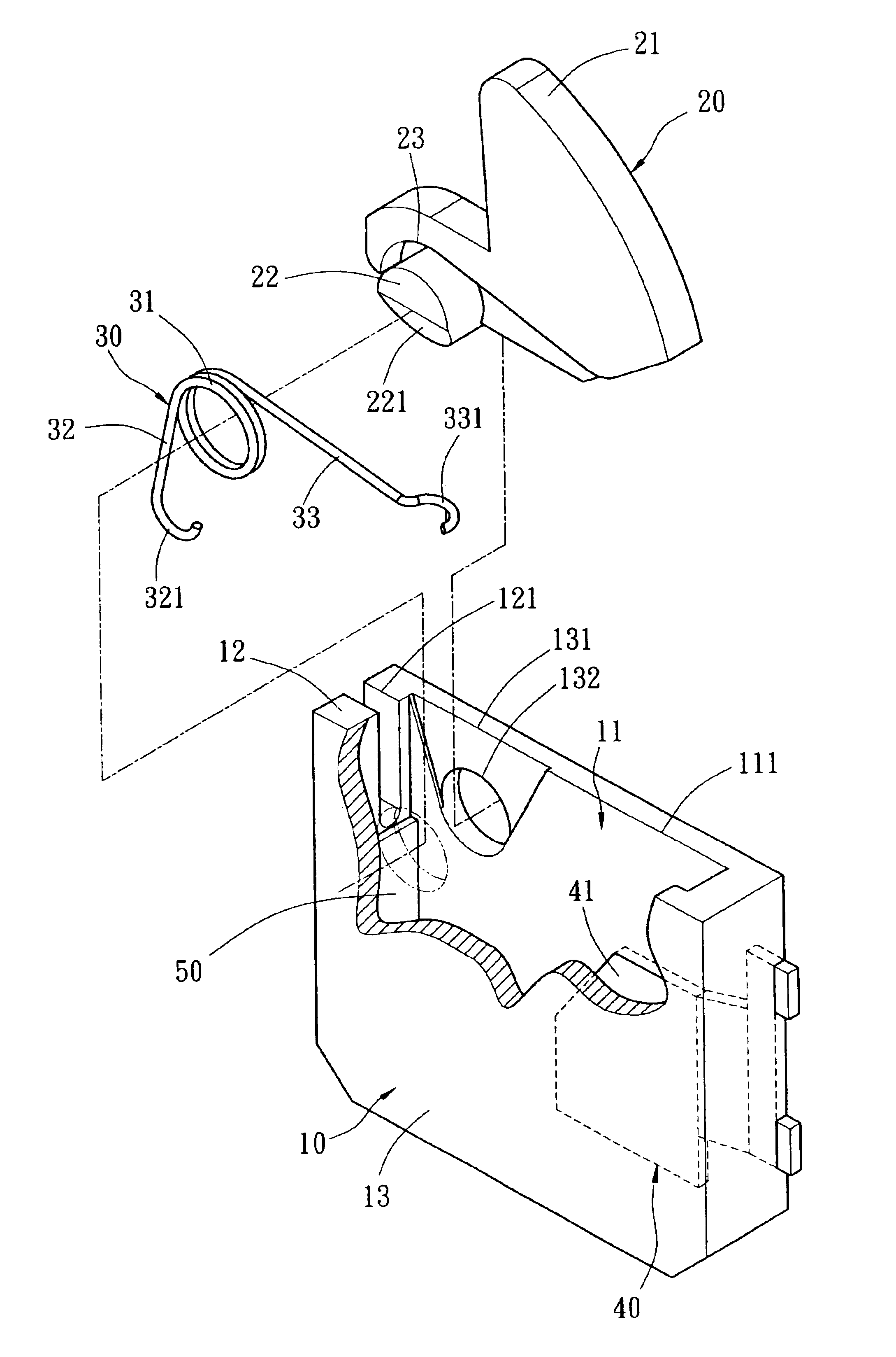
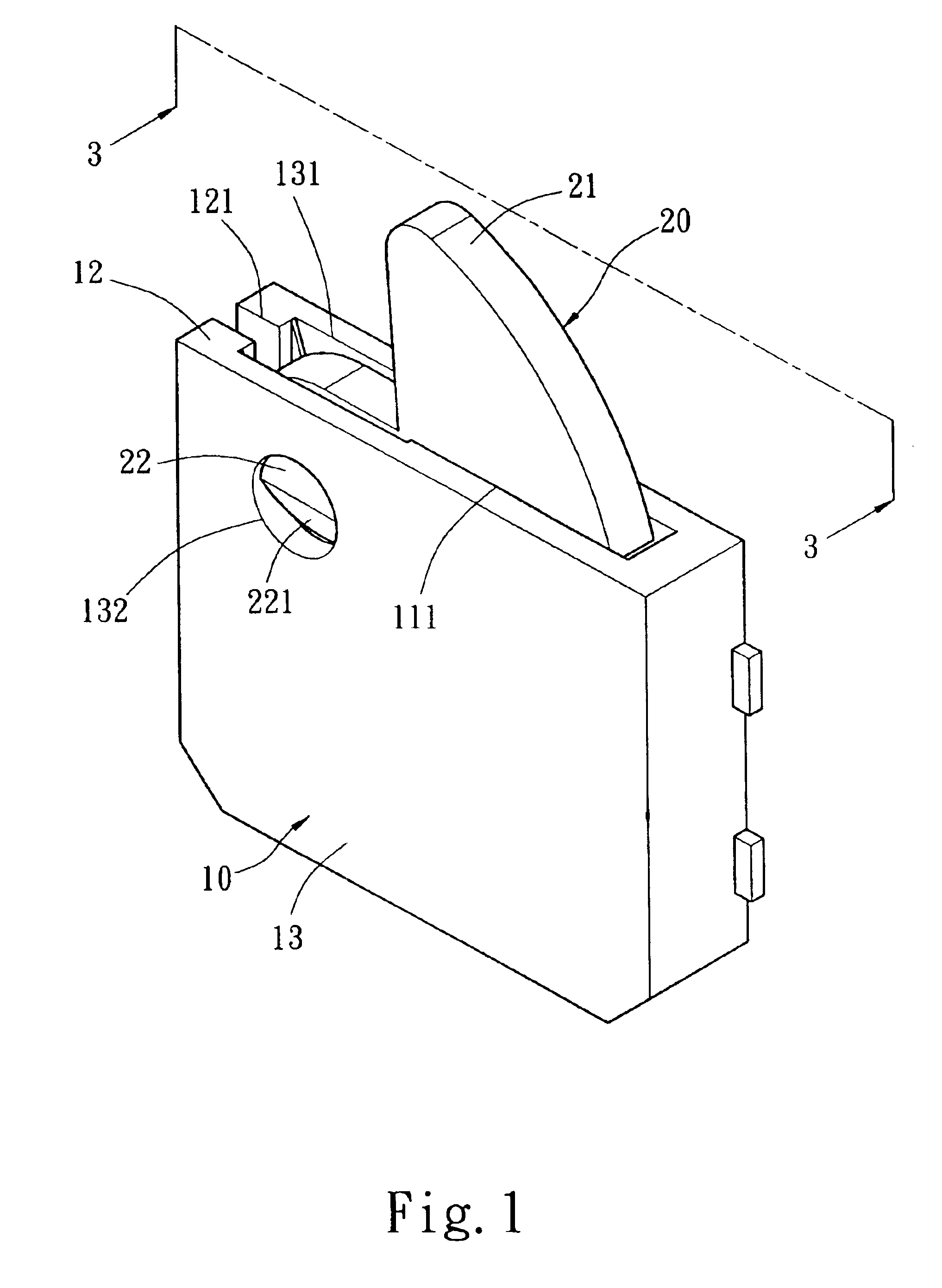
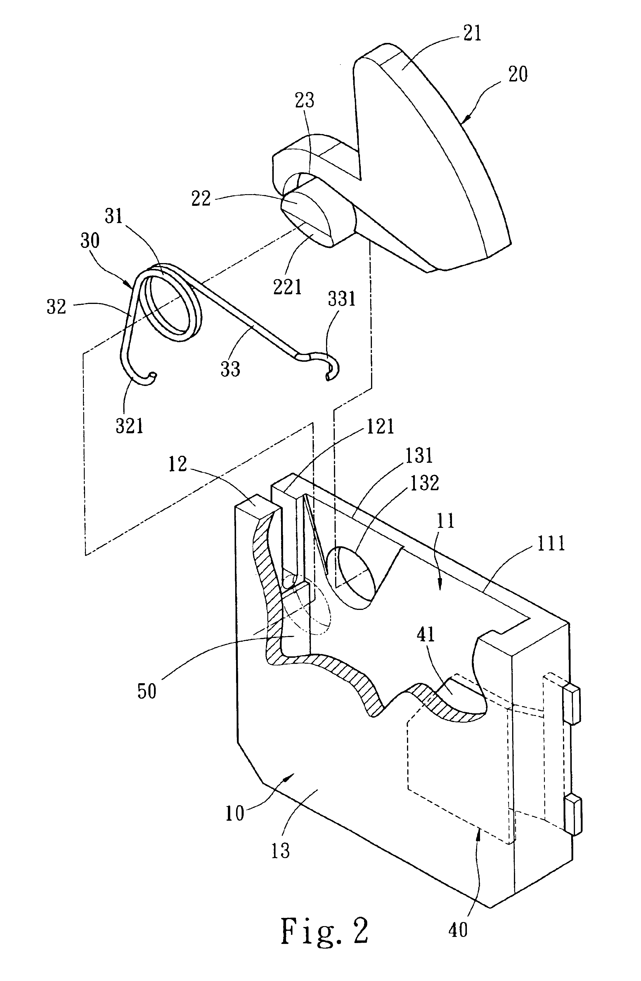
[0017]Please refer to FIGS. 1 to 4 for the present invention. The microswitch of the invention comprises: a main body 10 having a chamber 11 therein; a first conductive terminal 50 and a second conductive terminal 40 disposed on the chamber, and the first and second terminals 50, 40 being vertically disposed in the chamber 11; a press button 20 disposed in the chamber 11 for supporting and allowing a free rotation on the main body 10; a force acting section 21 disposed at the bottom of the press button 20 for providing an elastic force to push the press button 20 up and protruded from the main body 10; and a resilient component 30 having a first conductive section 32 and a second conductive section 33 for contacting the first conductiv...


PUM


Abstract

A microswtich that is easy to assemble and manufacture is provided. The microswitch constantly keeps the first conductive section of a resilient component for opening / closing an electrical switch in contact with the first conductive terminal in the main body of the microswitch, and houses a plate-shaped second conductive section with a contact surface inside the main body of the microswtich, so that the second conductive section of the resilient component is driven by a press button on the contact surface of the second conductive terminal to preset the signal from an initial connection state to a final connection state in order to increase the distance required for controlling the signal connection and allow the resilient component to have an effective deformation and provide the best resilience of the press button.

Description

[0001]This is a Continuation-in-part (CIP) application of Ser. No. 10 / 751,407, now U.S. Pat. No. 6,797,904, filed on Jan. 6, 2004, entitled “Microswitch”.FIELD OF THE INVENTION[0002]The present invention generally relates to microswitches, more particularly to a microswitch that provides several operating directions for switching on / off an electric contact point.BACKGROUND OF THE INVENTION[0003]In view of the low precision of manufacturing and assembling “small switches” as disclosed in the R.O.C. Patent Publication No. 517254 and “lever switches” as disclosed in the U.S. Pat. No. 6,559,401, the inventor of this invention had made improvements over the foregoing prior arts and filed a R.O.C. patent application entitled “Microswitch (II)”. Such patent application granted and published with Publication No. 562228 discloses an easy-to-assemble and easy-to-manufacture microswitch without changing the volume of the existing products or requiring a complicated manufacturing process or a s...

Claims


Application Information

Patent Timeline
Patent Type & Authority Patents(United States)
IPC IPC(8): H01H1/44H01H1/12H01H23/00H01H21/28
CPCH01H1/44H01H21/282H01H21/24
Inventor NI, YU-TING
Owner ZIPPY TECH
Why Eureka
Try Eureka