System and method for table/gantry alignment in imaging systems

a technology of imaging system and table, applied in the field of system and method for aligning the patient table and the gantry in the imaging system, can solve the problems of inaccuracy of images and similar issues between the ct and pet scans

Inactive Publication Date: 2005-07-12
GENERAL ELECTRIC CO
View PDF14 Cites 33 Cited by
  • Summary
  • Abstract
  • Description
  • Claims
  • Application Information

AI Technical Summary

Problems solved by technology

Without correct placement of the patient in the scanning field of view, the imagers will gather data that is not properly aligned, leading to inaccurate images.
In PET imaging systems, these issues often arise when performing a multiple axial field of view (AFOV) study.
In PET-CT studies, similar issues arise between the CT and PET scans.

Method used


Image

  • System and method for table/gantry alignment in imaging systems
  • System and method for table/gantry alignment in imaging systems
  • System and method for table/gantry alignment in imaging systems

Examples


Embodiment Construction

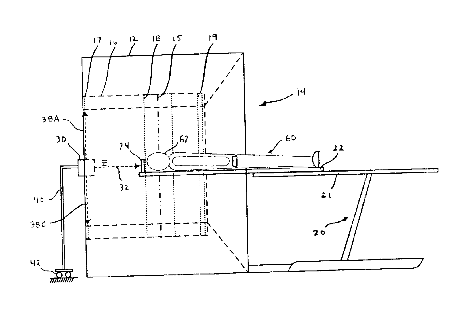
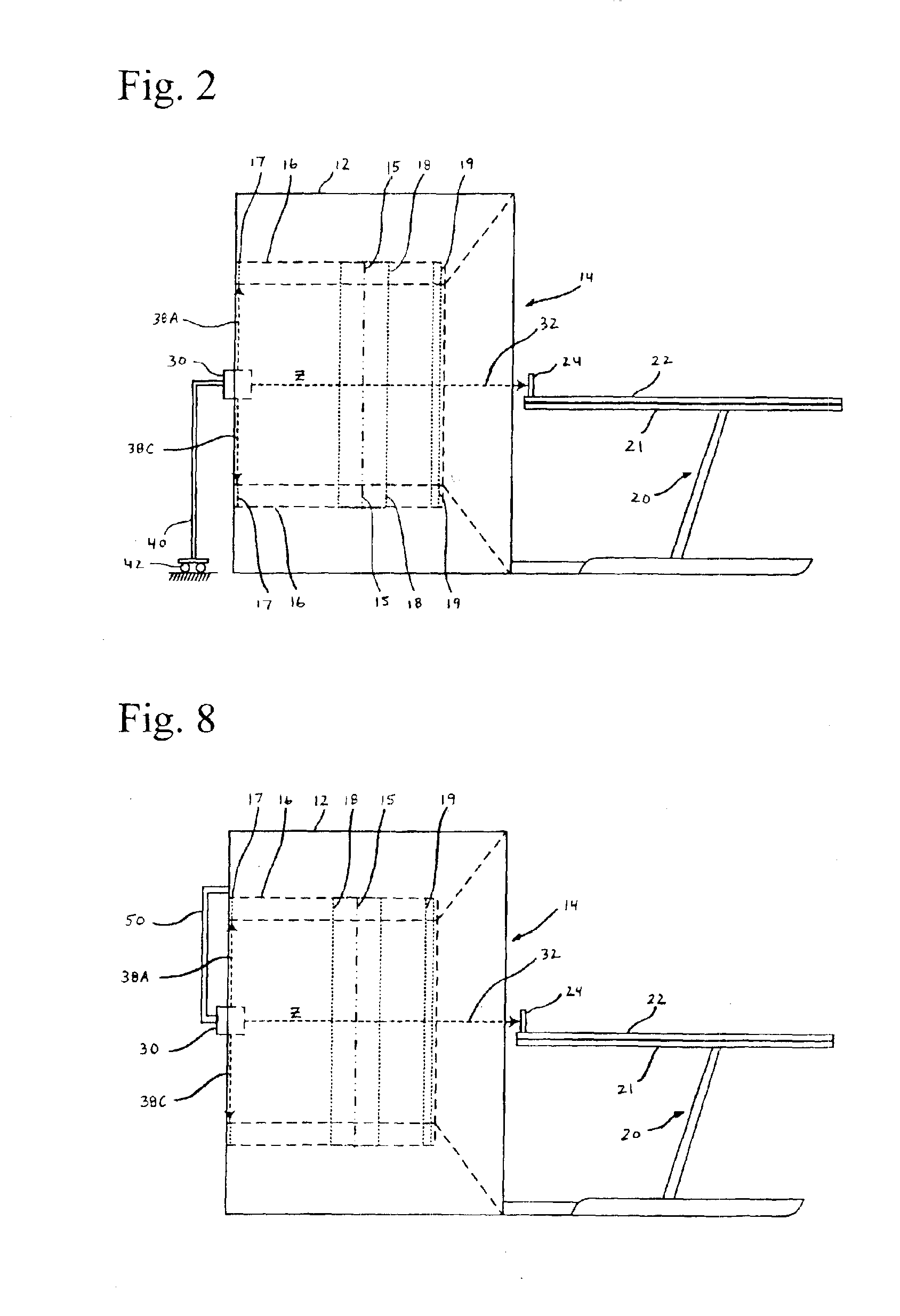
[0016]In an imaging system including a gantry having a patient bore, and a patient table having a cradle, a method of aligning the cradle with a scan plane in the patient bore is disclosed. The method comprises positioning a laser device relative to the patient bore, the laser device producing an alignment laser beam projecting along an axis of the patient bore normal to the scan plane. The method further comprises aligning the cradle of the patient table such that when the cradle is translated into the scan plane in the patient bore, the alignment laser beam intersects a target point on a positioning target on the cradle.

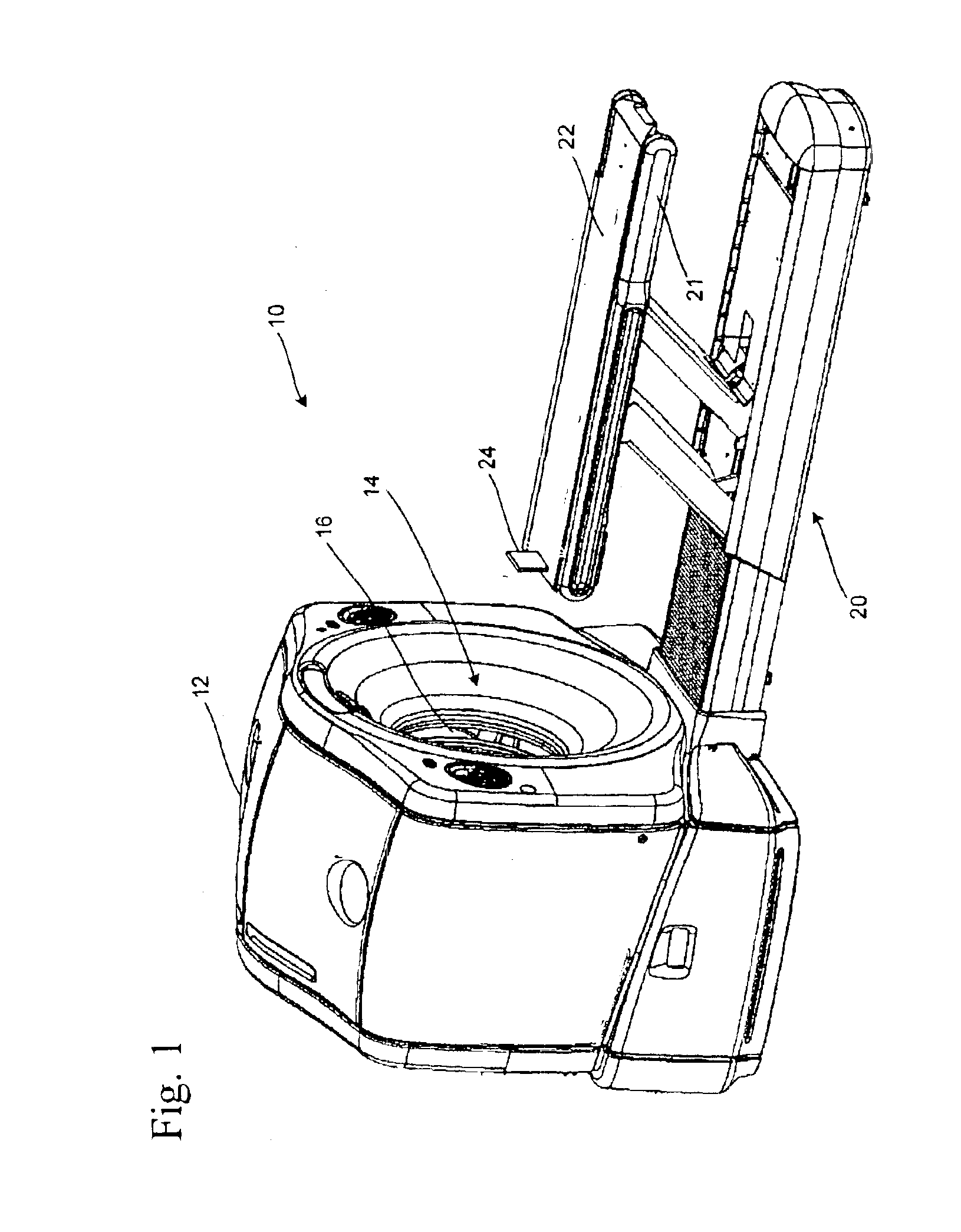
[0017]FIG. 1 is a perspective view of an imaging system in accordance with one embodiment of the invention. Imaging system 10 includes gantry 12, patient table 20 and an operator workstation (not illustrated). The operator workstation typically commands and controls the processes and mechanical operation of the imaging system.

[0018]As shown in FIG. 1, gantry 12 has...


PUM


Abstract

In an imaging system including a gantry having a patient bore, and a patient table having a cradle, a method of aligning the cradle with a scan plane in the patient bore is disclosed. The method comprises positioning a laser device at least partially within the patient bore, the laser device producing an alignment laser beam projecting along a center axis of the patient bore normal to the scan plane. The method further comprises aligning the cradle of the patient table such that when the cradle is translated into the scan plane in the patient bore, the alignment laser beam intersects a positioning target on the cradle.

Description

BACKGROUND OF THE INVENTION[0001]The invention relates generally to systems and methods for aligning the patient table and gantry in medical imaging systems.[0002]For imaging systems, such as Positron Emission Tomography (PET) and Computed Tomography (CT) imagers, the alignment of a patient within the imaging area can be very important to the success of the imaging. Without correct placement of the patient in the scanning field of view, the imagers will gather data that is not properly aligned, leading to inaccurate images.[0003]In PET imaging systems, these issues often arise when performing a multiple axial field of view (AFOV) study. In PET-CT studies, similar issues arise between the CT and PET scans. PET is a procedure that allows a physician to examine the heart, brain, and other organs, by producing images that show the molecular functioning of an organ or tissue. PET imagers include, among other components, a patient table with a cradle, a gantry and an operating workstation...

Claims


Application Information

Patent Timeline
Patent Type & Authority Patents(United States)
IPC IPC(8): A61B6/04A61B6/08
CPCA61B6/04A61B6/08A61B6/5276
Inventor WOLLENWEBER, SCOTT DAVID
Owner GENERAL ELECTRIC CO
Why Eureka
Try Eureka