Facility management system and facility management method

a technology of facility management and management system, which is applied in the direction of adaptive control, static/dynamic balance measurement, instruments, etc., can solve the problems of increasing the cost of introducing the dedicated operation monitor device, increasing the cost of product development, so as to reduce the cost of device development and the cost of introduction, the effect of fast maintenan

Inactive Publication Date: 2005-07-12
MITSUBISHI ELECTRIC CORP
View PDF5 Cites 9 Cited by
  • Summary
  • Abstract
  • Description
  • Claims
  • Application Information

AI Technical Summary

Benefits of technology

[0022](a) For an owner of a building it is possible to reduce the introduction cost of facilities or devices for use in the maintenance of electric facilities, and the owner of the building can receive the fast maintenance for the electric facilities installed in the building;
[0023](b) For a facility maintenance company it is possible to reduce the cost necessary for developing and introducing facilities or devices for use in the maintenance of the electric facilities, and the facility maintenance company can provide the fast maintenance to the owner of the building;
[0025](d) In the electric facility manufacture it is possible to reflect the quality information in the future development for the products and to settle the maintenance cost for the electric facilities with certainly.
[0030]Accordingly, the present invention has the effect for the facility maintenance company that it is possible to reduce the cost of the development of the devices and the cost of the introduction of the devices for maintenance, and possible to provide the fast maintenance to the owner of the building.
[0031]Still further, the present invention has the effect for the electric facility manufacture that it is possible to provide to the owner of the building the manufacture's responsibility speedily, also possible to reflect the quality information in the future product development, and also possible to settle the maintenance cost for the electric facilities from the owner or the facility maintenance company with certainly.

Problems solved by technology

This causes the increasing of the cost to introduce the dedicated operation monitor device 120 and also occurs a drawback that the facility maintenance company 200 cannot perform the fast repairing according to the content of the defect.
This causes the increase of the costs for the product development and the introduction of the remote monitor device 210.
This case cannot provide the fast maintenance to the owner 100 of the building.
Accordingly, it is difficult that the manufacture 300 provides the fast maintenance and the manufacture's responsibility to the owner 100 of the building when the defect happens in the electric facilities.
Furthermore, the manufacture 300 cannot improve the electric facilities in a future product development using the quality information on the market.
Still further, the conventional facility maintenance system has a drawback that it is difficult for the electric facility manufacture 300 to settle the maintenance cost of the electric facilities 110 form the facility maintenance company 200 or the owner 100.
But, when the maintenance operator is different from the maintenance circumstance provider (such as the electric facility manufacture 300), it is difficult to suppress the use of the maintenance environment by the maintenance operator (namely, the facility maintenance company 200) without warning.
For example, the conventional facility management system has a problem in which it is difficult to protect and keep the correct benefit for the maintenance cost, the repairing cost and the cost to provide various information supplied by the maintenance circumstance provider such as the electric facility manufacture 300.

Method used


Image

  • Facility management system and facility management method
  • Facility management system and facility management method
  • Facility management system and facility management method

Examples


embodiment

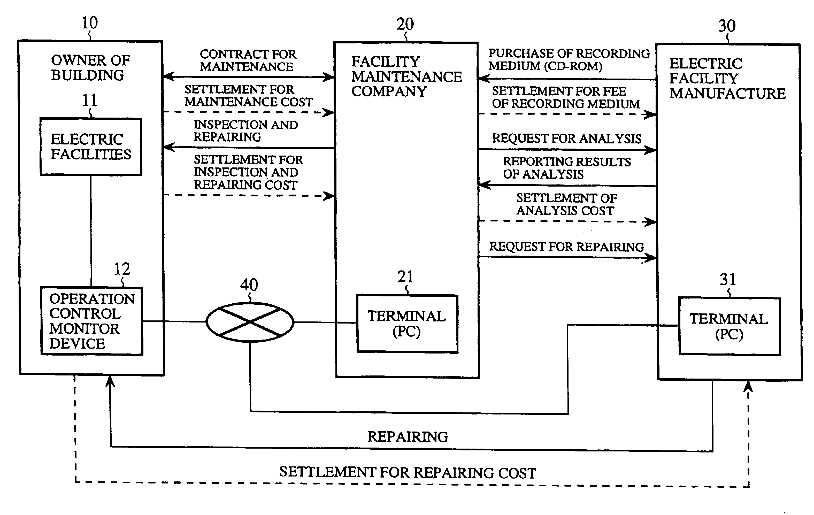
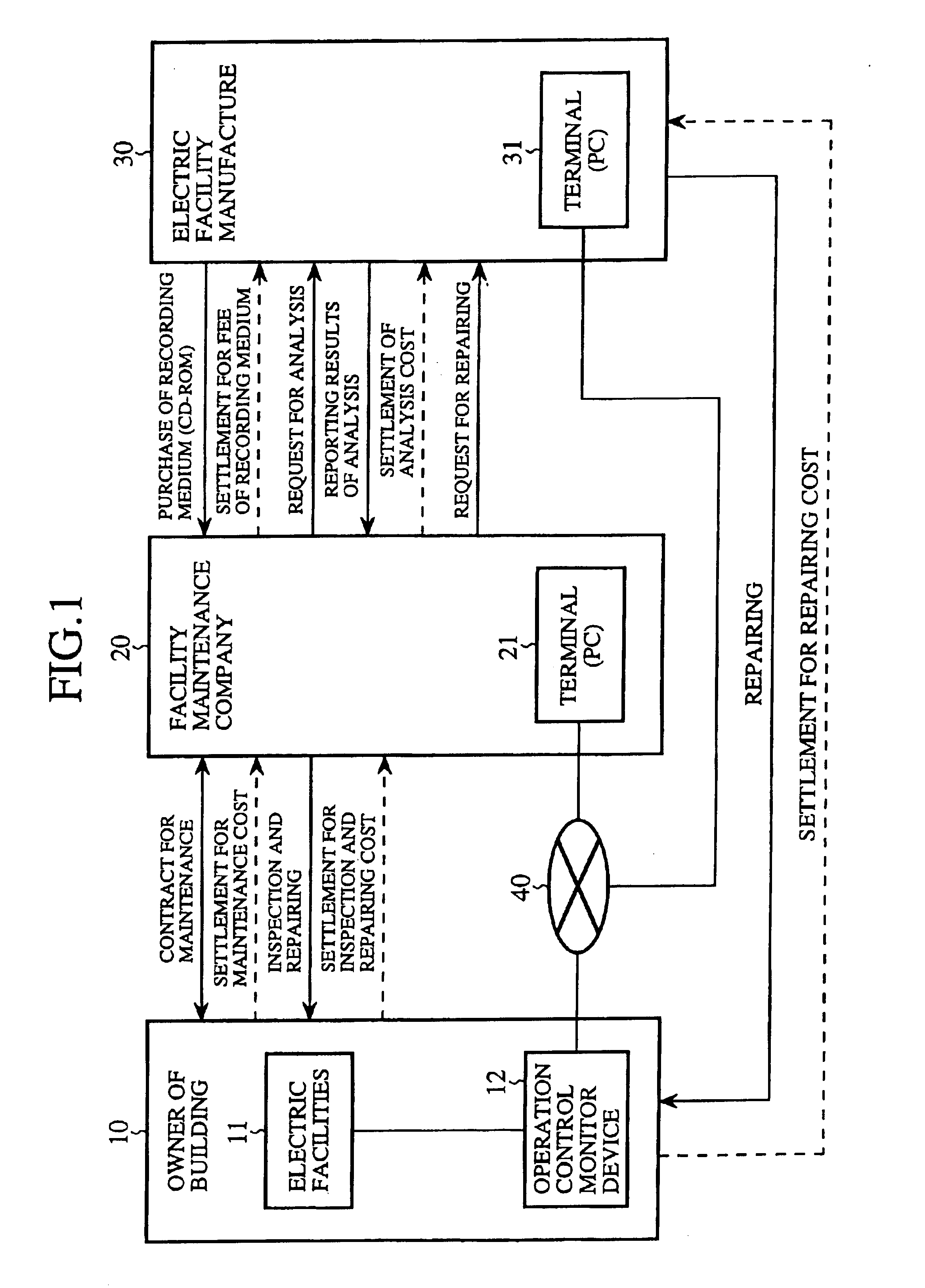
[0038]FIG. 1 is a diagram showing a configuration of the facility management system according to an embodiment of the present invention. In FIG. 1, reference number 10 designates the owner of a building, 11 denotes electric facilities such as an air conditioning system installed in the building of the owner 10. Reference number 12 indicates an operation control monitor device for controlling the entire operation of the electric facilities 11 and monitoring the operation state of the electric facilities 11 and collecting and transmitting monitor data items such as operation data items.

[0039]In FIG. 1, reference number 20 designates a facility maintenance company for performing the maintenance and inspection of the electric facilities 11 installed in the building of the owner 10. Reference number 21 denotes a terminal (as a first terminal) such as a personal computer installed in the facility maintenance company 20, 30 designates an electric facility manufacture for manufacturing the ...


PUM


Abstract

An owner concludes with a facility maintenance company a contract for maintenance of electric facilities and an operation control monitor device installed in a building of the owner. The electric facility manufacturer gives the company permission to access the device from a terminal through the Internet as a communication network. The company receives continuous monitor data items of the electric facilities collected by the device. The manufacturer accesses the device from a terminal through the network and also receives the continuous monitor data items of the electric facilities.

Description

BACKGROUND OF THE INVENTION[0001]1. Field of the Invention[0002]The present invention relates to a facility management system and a facility management method for maintaining and inspecting electric facilities such as an air conditioning system installed in a building.[0003]2. Description of the Related Art[0004]FIG. 4 is a diagram showing a conventional facility management system. In FIG. 4, reference number 100 designates an owner of a building, 110 denotes one or more electric facilities installed in the building of the owner 100, 130 indicates an operation controller for controlling the entire operation of the electric facilities 110, and 120 designates an operation monitor device for monitoring the operation of the electric facilities 110 and transmitting monitor data items to outside.[0005]Reference number 200 designates a facility maintenance company performing the maintenance and inspection for the electric facilities 110 installed in the building of the owner 100, and 210 d...

Claims


Application Information

Patent Timeline
Patent Type & Authority Patents(United States)
IPC IPC(8): G06Q10/00G06Q50/10G06Q50/00
CPCG06Q10/06
Inventor MASUI, HIROTAKAIKEDA, TAKASHIANDO, MASAFUMIHATTORI, SHINJITAKATA, SHIGEOHAYAKAWA, HIDESUKE
Owner MITSUBISHI ELECTRIC CORP
Why Eureka
Try Eureka