Vehicle headlamp system

a headlamp system and vehicle technology, applied in vehicle headlamps, optical radiation measurement, lighting support devices, etc., can solve the problem of not being able to achieve beam emission with a luminous intensity distribution, and achieve the effect of increasing the travel safety of the vehicle and increasing the distan

Inactive Publication Date: 2005-07-19
KOITO MFG CO LTD
View PDF15 Cites 12 Cited by
  • Summary
  • Abstract
  • Description
  • Claims
  • Application Information

AI Technical Summary

Benefits of technology

[0011]As described above, the vehicle headlamp system according to the invention is such that the lamp unit is contained in the lamp body of each headlamp to carry out forward beam emission with the predetermined luminous intensity distribution by using the lamp unit. Further, the vehicle headlamp system is provided with the vehicle-to-vehicle distance measuring means for measuring the vehicle-to-vehicle distance between one's own vehicle and a preceding vehicle, and when the speed of one's own vehicle exceeds a predetermined value, the luminous intensity distribution of the lamp unit is varied by the variable luminous intensity control means according to the vehicle-to-vehicle distance therebetween. Therefore, the following operation and / or working effect is achievable.
[0012]With an increase in the vehicle speed to a certain degree, importance is attached to securing sufficient forward visibility of the road surface ahead of the vehicle in view of increasing the travel safety of the vehicle. As the luminous intensity distribution of the lamp unit is varied with the distance to a preceding vehicle according to the invention, remote visibility is increased by turning the luminous intensity distribution slightly upward when the vehicle-to-vehicle distance is long, whereas the luminous intensity distribution is turned slightly downward when the vehicle-to-vehicle distance is short in order to prevent giving the driver of a preceding vehicle a glare, whereby beam emission can be carried out with a luminous intensity distribution according to the travel conditions of the vehicle.
[0013]With the arrangement above, by adapting the variable luminous intensity control means to fix the luminous intensity distribution while the speed of one's own vehicle is kept at a predetermined value or lower, one can prevent an unpleasant feeling that something is wrong, resulting from the change of the low-beam luminous intensity distribution, from being given to the driver of a preceding vehicle in a low vehicle speed zone in which the remote visibility is not so important.

Problems solved by technology

However, an arrangement for varying a luminous intensity distribution only in response to the vehicle speed is not capable of beam emission with a luminous intensity distribution corresponding to the travel conditions of a vehicle.

Method used


Image

  • Vehicle headlamp system
  • Vehicle headlamp system
  • Vehicle headlamp system

Examples


Embodiment Construction

[0024]An embodiment of the present invention will now be described with reference to the drawings.

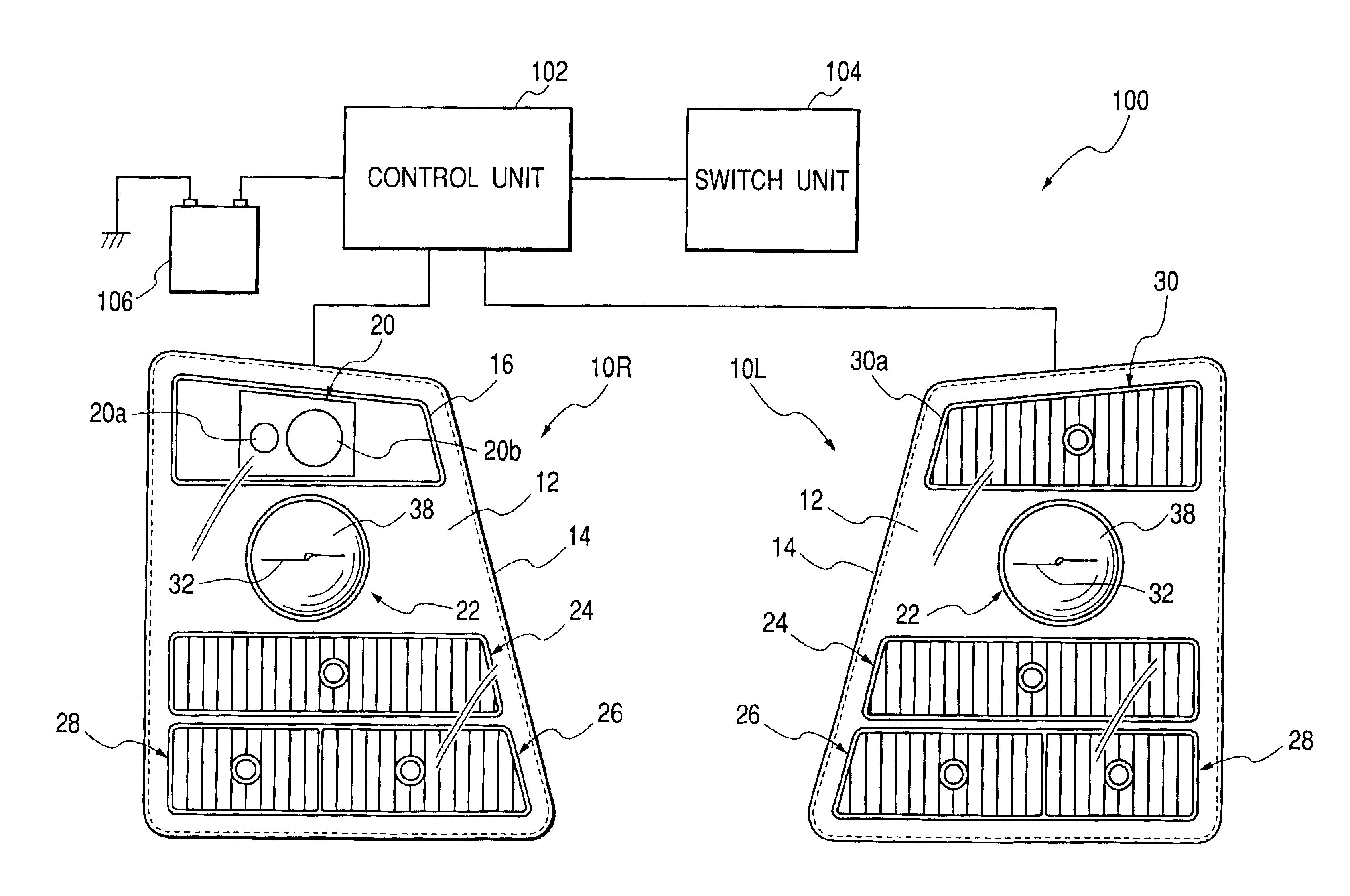
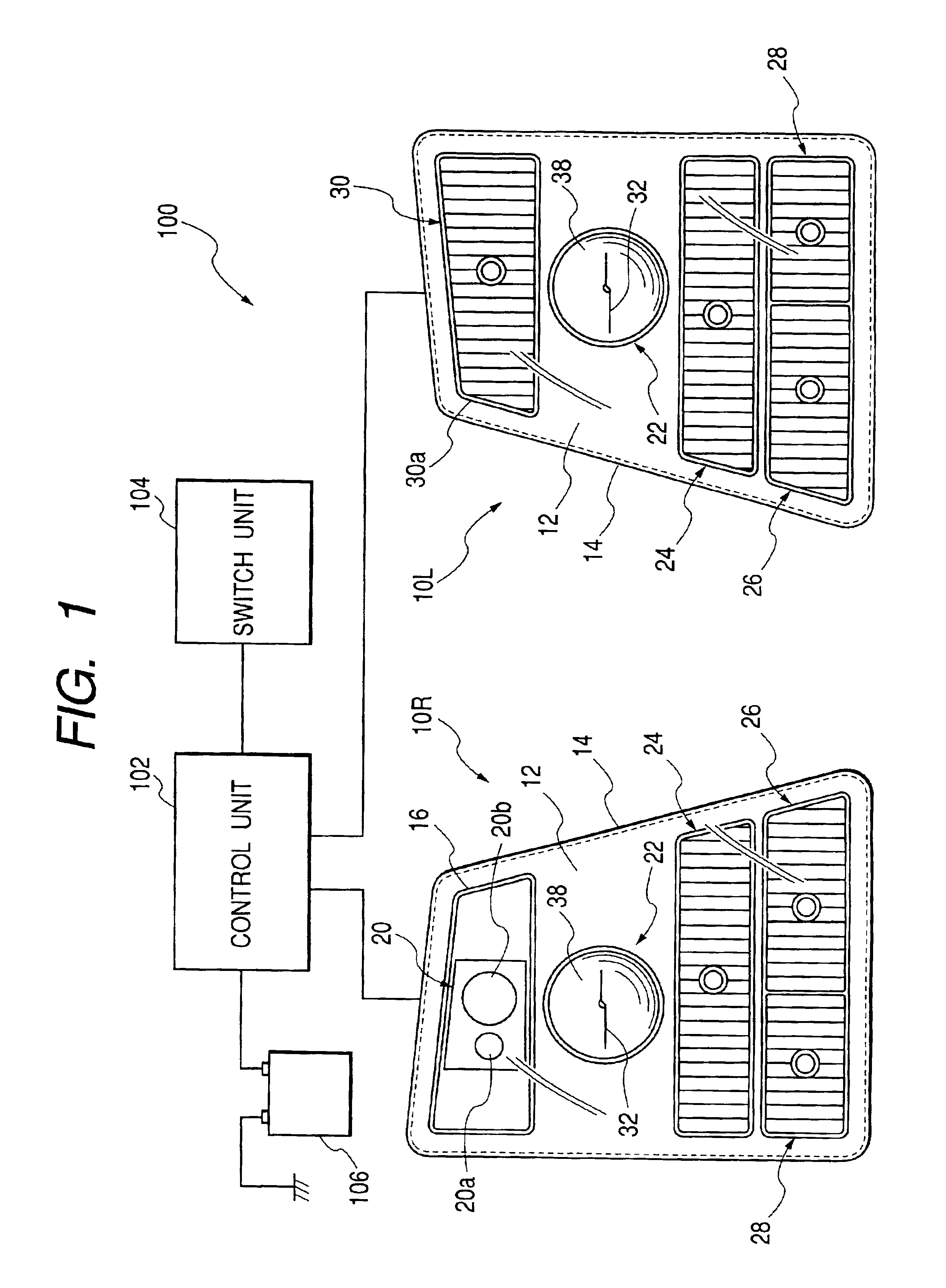
[0025]FIG. 1 is an overall block diagram illustrating a vehicle headlamp system embodying the invention.

[0026]As shown in FIG. 1, a vehicle headlamp system 100 is provided to a large-sized vehicle such as a truck and comprises a pair of left- and right-side headlamps 10L and 10R disposed in the front end portion of a vehicle, a vehicle-to-vehicle distance sensor 20 (a vehicle-to-vehicle distance measuring means) incorporated in the right-side headlamp 10R, a control unit 102 (a variable luminous intensity control means) connected to the headlamps 10L and 10R, a switch unit 104 connected to the control unit 102, and a battery power supply 106 connected to the control unit 102.

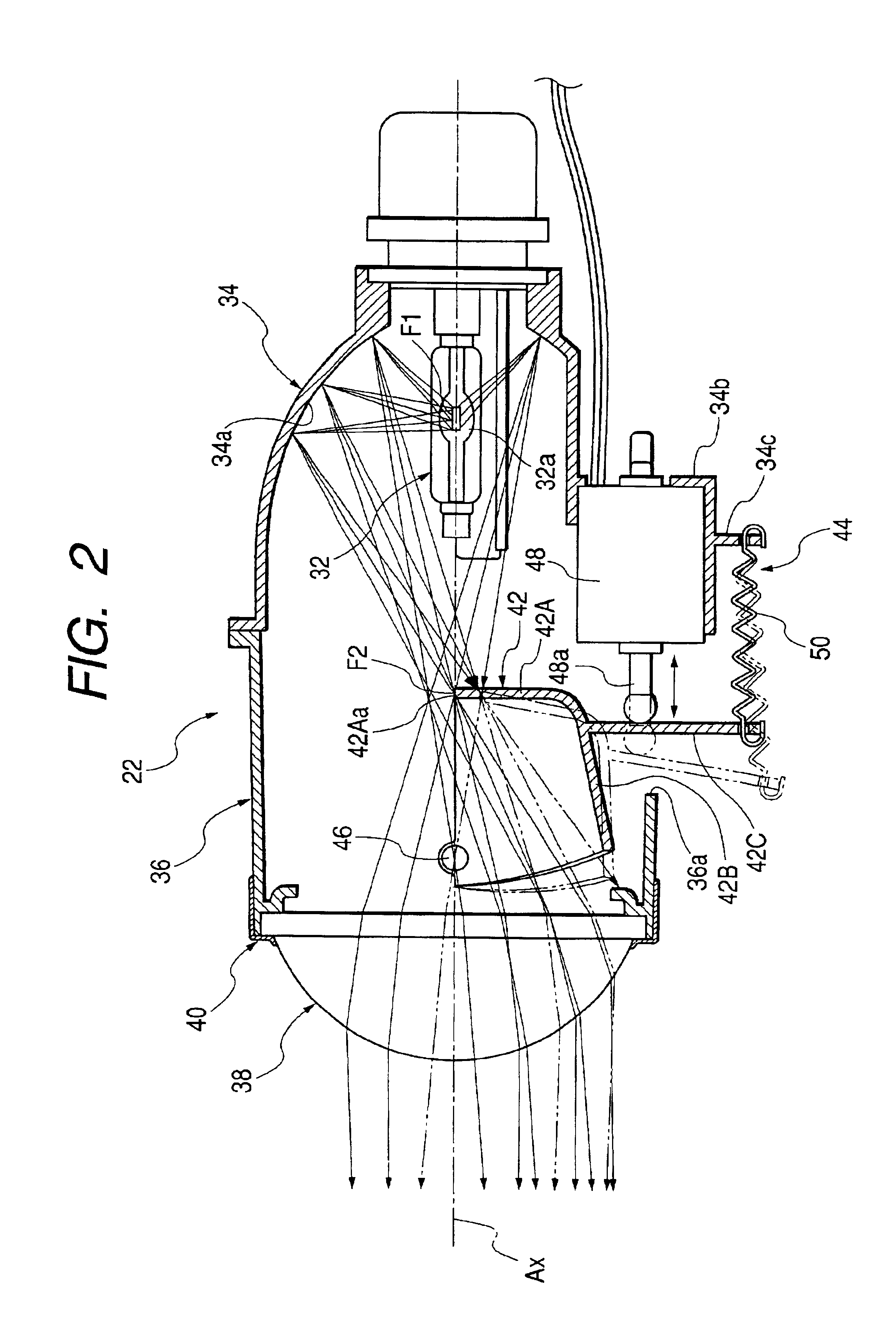
[0027]In each of the headlamps 10L and 10R, a lamp unit 22 is formed of a headlamp body, various lamps and the like that are housed in a lamp chamber formed with a transparent cover 12 and a lamp body 14.

[0028]More ...


PUM


Abstract

A vehicle headlamp system with headlamps, each of which contains a lamp unit for emitting beams forward with a predetermined luminous intensity distribution. The system carries out beam emission with a luminous intensity distribution corresponding to the travel conditions of a vehicle. In an implementation, when the speed of one's own vehicle exceeds 25 km/h, a low-beam luminous intensity distribution P(L) is varied according to a vehicle-to-vehicle distance in relation to a preceding vehicle. Remote visibility is increased by positioning a cut-off line slightly upward when the vehicle-to-vehicle distance L is long, whereas when the vehicle-to-vehicle distance L is short the cut-off line is lowered slightly in order not to give a glare to the driver of the preceding vehicle. But when the vehicle speed V is 25 km/h or lower, the low-beam luminous intensity distribution P(L) is fixed at a downward position which prevents glare and prevents an unpleasant feeling that something is wrong from being given to the driver of the preceding vehicle resulting from the change of the low-beam luminous intensity distribution P(L).

Description

BACKGROUND OF THE INVENTION[0001]The present invention relates to a vehicle headlamp system with headlamps, each of which contains a lamp unit in a lamp body.[0002]There are conventionally known vehicle headlamps containing a lamp unit in a lamp body, and also those which are designed to vary the luminous intensity distribution formed by such a lamp unit in response to vehicle speed[0003]However, an arrangement for varying a luminous intensity distribution only in response to the vehicle speed is not capable of beam emission with a luminous intensity distribution corresponding to the travel conditions of a vehicle.SUMMARY OF THE INVENTION[0004]The present invention, in view of the foregoing problem, provides a vehicle headlamp system with headlamps, each of which contains a lamp unit within a lamp body for emitting beams forward with a predetermined luminous intensity distribution in such a manner as to carry out beam emission with a luminous intensity distribution corresponding to ...

Claims


Application Information

Patent Timeline
Patent Type & Authority Patents(United States)
IPC IPC(8): B60Q1/08B60Q1/04F21V14/08F21V14/00B60Q1/14B60Q1/18F21S8/10F21W101/10F21Y101/00
CPCB60Q1/0023B60Q1/085B60Q1/18B60Q2300/054B60Q2300/112B60Q2300/122B60Q2300/142B60Q2300/312B60Q2300/41F21S48/1768F21S41/683
Inventor MAKITA, HIROYUKIKIMURA, TAKESHIKUSAGAYA, MASAHIRO
Owner KOITO MFG CO LTD
Why Eureka
Try Eureka