
Dynamic isolating mount for processor packages

a technology for microprocessors and mounting brackets, which is applied in the direction of sustainable manufacturing/processing, final product manufacturing, lighting and heating apparatus, etc. it can solve the problems of increasing the power consumption of microprocessors, increasing the complexity of the process, and increasing the complexity of the components. , to achieve the effect of preventing/minimizing cracking, preventing/minimizing cracking, and increasing the lifetime of the processor

Inactive Publication Date: 2005-07-19
HEWLETT-PACKARD ENTERPRISE DEV LP +1
View PDF40 Cites 25 Cited by
  • Summary
  • Abstract
  • Description
  • Claims
  • Application Information

AI Technical Summary

Benefits of technology

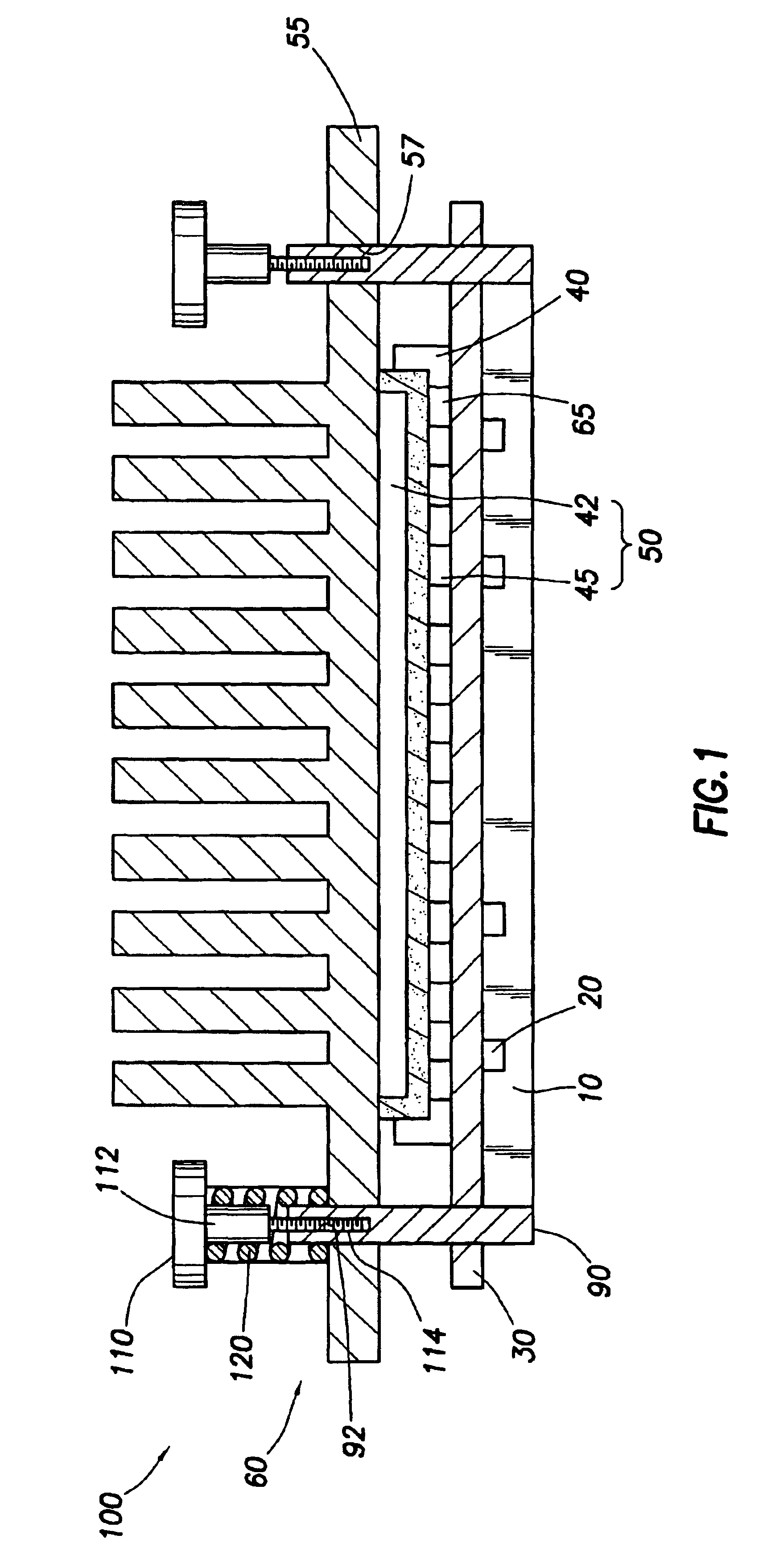
[0012]The present invention relates to a method and apparatus that prevents / minimizes cracking in the ceramic body of chips. The ability to prevent / minimize cracking can ensure successful operation and substantially increase processor lifetime.
[0015]In accordance with yet another preferred embodiment of the present invention, a method for preventing cracking of the ceramic body of a microprocessor includes placing a dynamic isolating mount on a printed wiring board where the printed wiring board contacts the processor.

Problems solved by technology

Although generally satisfactory, soldering a component directly to the board makes it difficult and costly to change that component should it be desired or necessary to replace one component with another.
As technology has progressed, some chips (i.e., microprocessors) have become more powerful and accordingly consume more electrical power.
This increase in power usage causes the chips to become hotter and larger heat sinks are required to dissipate the increased thermal load.
Mounting a large chip with a heat sink in an interposer socket may be problematic in the face of shock / vibration loads.
For example, motion caused by a fan, opening and closing cabinet doors in a rack of computers, seismic activity, and vibration induced by adjacent equipment may cause the ceramic body of a chip to crack and ultimately fail.
Obviously, this failure may cause the electrical component contained in the interposer to cease functioning as intended.

Method used


Image

  • Dynamic isolating mount for processor packages
  • Dynamic isolating mount for processor packages
  • Dynamic isolating mount for processor packages

Examples


Embodiment Construction

[0022]Currently, there is desire to mount CPUs in area array interposer sockets. The manner of mounting a CPU in an interposer socket requires supporting the ceramic body at discrete locations around the periphery of the device. Because the ceramic body of high performance processors is brittle, these support points can then become origins for cracks when the device is subjected to assembly and impact type forces. The present invention provides a positive means for controlling cracking in the ceramic body of the processor by providing assembly support and shock / vibration isolation through an energy dissipation device, or dynamic isolating mount.

[0023]The preferred embodiment of the invention is described below in the context of a processor chip and heat sink combination mounted on a circuit board with an interposer socket. It should be noted, however, that the chip need not be a processor nor is the heat sink required. Broadly, the invention is useful to reduce vibration for any typ...


PUM


Abstract

The present invention relates to a method and apparatus that prevents / minimizes cracking in the ceramic body of processors. The ability to prevent / minimize cracking can ensure successful operation and substantially increase processor lifetime. The present invention discloses a device for maintaining a microprocessor in a desired relationship with a printed wiring board while limiting the transmission of shock and vibrational motion to and from the processor includes a printed wiring board, a processor, and a dynamic isolating mount compressed between the printed wiring board and the processor, wherein the processor maintains the dynamic isolating mount in a compressed state such that the dynamic isolating mount bears on the printed wiring board.

Description

CROSS-REFERENCE TO RELATED APPLICATIONS[0001]This is a continuation of application Ser. No. 09 / 919,295 filed on Jul. 31, 2001, now U.S. Pat. No. 6,833,489 which is hereby incorporated by reference herein.[0002]The subject matter of the present application is related to the subject matter of co-pending application entitled “Tunable Vibration Damper for Processor Packages,” incorporated herein by reference.STATEMENT REGARDING FEDERALLY SPONSORED RESEARCH OR DEVELOPMENT[0003]Not applicable.BACKGROUND OF THE INVENTION[0004]1. Field of the Invention[0005]The present invention generally relates to protecting microprocessors from overstress caused by sudden forces or impacts. More particularly, the present invention relates to a dynamic isolating mount for a microprocessor package.[0006]2. Background of the Invention[0007]For many decades, circuit boards, such as those used in computers, have been manufactured by attaching electrical components to the board. In some cases, the components a...

Claims


Application Information

Patent Timeline
IPC IPC(8): H01L23/40H01L23/498H01L23/48H01L23/34H01L23/00H05K3/30H05K1/02H05K3/34
CPCH01L23/4006H01L23/49827H01L23/562H05K3/303H05K1/0271H05K3/3436H05K2201/0133H05K2201/10734H05K2201/2036H05K2201/2045H01L2224/16Y02P70/50
Inventor CALLAHAN, DANIEL L.IANNUZZELLI, RAYMOND J.
Owner HEWLETT-PACKARD ENTERPRISE DEV LP
Learn More