Floor shape estimation system of legged mobile robot

a mobile robot and floor technology, applied in the field of floor shape estimation system of a legged mobile robot, can solve the problems of not conducting a posture stabilization control to manipulate the floor, disadvantageous increase in estimation errors, and prior art techniques, and achieve the effect of improving the robot posture stabilization

Inactive Publication Date: 2005-07-19
HONDA MOTOR CO LTD
View PDF10 Cites 39 Cited by
  • Summary
  • Abstract
  • Description
  • Claims
  • Application Information

AI Technical Summary

Benefits of technology

[0009]An object of the present invention is to solve the problem and to provide a floor shape estimation system of a legged mobile robot which can accurately conduct simultaneous floor shape estimation which has been difficult in the prior art, i.e., which can accurately estimate a floor shape, more specifically the inclination of the surface with which the foot is in contact and a height difference between the surfaces with which the feet are in contact, at the same time, in other words in a composite manner.

Problems solved by technology

However, this prior art technique has the following problems.
Specifically, it can not conduct a posture stabilization control to manipulate the floor reaction force until the foot has landed on the floor to profile the floor surface.
Further, if a member made of a soft material such as rubber is applied to the foot sole so as to enhance grip, the structure would disadvantageously increase estimation error.
Further, when the foot does not land on the floor completely, i.e., when the foot does not land with its sole surface-contact with the floor, it can not estimate a floor height correctly during the two-leg supporting period.
Further, when the feet are in contact with the floor completely, for example, at the time of holding itself upright, it can not estimate, at the same time, the inclination of a surface with which each foot is in contact and a height difference between the surfaces with which the feet are in contact.
Furthermore, since it can only estimate the floor shape at an instant of foot landing, if the floor deforms after landing, it can no longer estimate the deformed shape.
However, during the two-leg supporting period it can only estimate the inclination of a surface that intersects or adjoins the surfaces with which the feet are in contact, whilst during one-leg supporting period it can only estimate the inclination of the surface with which the supporting leg foot is in contact.
In other words, this prior art technique can not estimate the inclinations at the same time.

Method used


Image

  • Floor shape estimation system of legged mobile robot
  • Floor shape estimation system of legged mobile robot
  • Floor shape estimation system of legged mobile robot

Examples


second embodiment

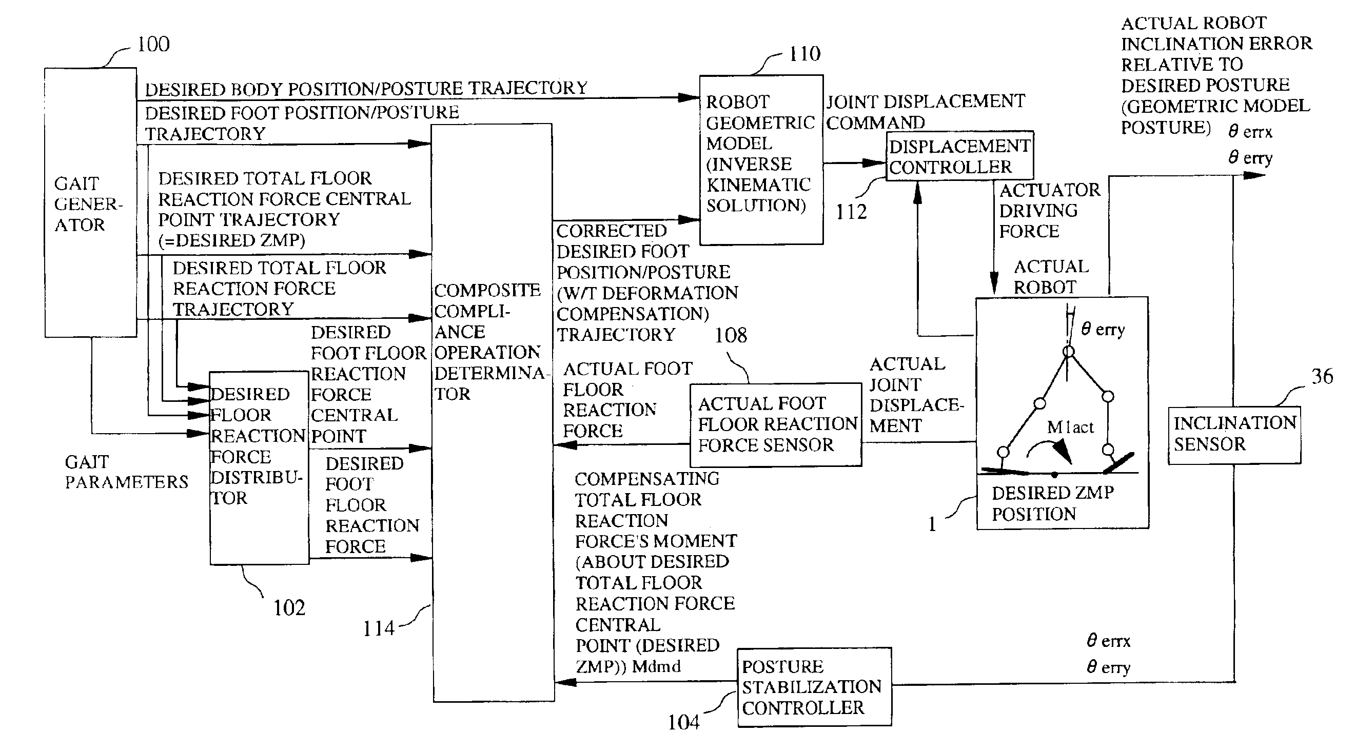
[0133]The manipulated variable for controlling the rotation of mode 1 is a moment component about the back-and-forth axis (X-axis) of the compensating total floor reaction force. The manipulated variable for controlling the rotation of Mode 2 is the moment component about the left-and-right axis (Y-axis) of the compensating total floor reaction force. Among the moment components of the compensating total floor reaction force, accordingly, it suffices if the moment component about the back-and-forth axis and that about the left-and-right axis are determined. Since the rest of the moment components are not used in this embodiment (and a second embodiment), they are set to zero.

[0134]From now on, the following definitions will be used. The moment component of compensating total floor reaction force is called a “compensating total floor reaction force's moment Mdmd” (more precisely, compensating total floor reaction force's moment Mdmd about the desired total floor reaction force centra...

first embodiment

[0432]Here, as mentioned in the first embodiment, θ fdbestmv is the estimated foot-to-foot floor inclination difference. And, θ dbv′ is the feet compensating angle with floor shape estimation and as illustrated in FIG. 42, is the sum of the feet compensating angle θ dbv and the estimated foot-to-foot floor inclination difference θ fdbestmv. Since current values of the feet compensating angle with floor shape estimation θ dbv′ and the estimated foot-to-foot floor inclination difference θ fdbestmv should be calculated from themselves, they should be stored and their most recent values should be used in the calculation.

[0433]It should be noted here that, when it is required to estimate the foot-to-foot floor inclination difference before a supposed timing at which the feet are to be landed, in order to improve the estimation accuracy, it is preferable to add the supposed feet interference angle θ dbintcmdv. However, the configuration to add the supposed feet compensating angle θ dbintc...


PUM


Abstract

A floor shape estimation system for a legged mobile robot, in particular a biped walking robot, which estimates a floor shape, more specifically a foot-to-foot floor inclination difference based on at least a control error of the total floor reaction force's moment and based on the estimated value and corrects a feet compensating angle based on the estimated value. Further, the system estimates a floor shape, more specifically a foot floor inclination difference based on at least a control error of the foot floor reaction force about a desired foot floor reaction force central point and corrects a foot compensating angle based on the estimated value. With this, it can accurately estimate the shape of a floor with which the robot is in contact. Further, if the floor shape is different from what has been supposed, it can produce the floor reaction force as desired by absorbing the influence of difference.

Description

TECHNICAL FIELD TO WHICH THE INVENTION RELATES[0001]The present invention relates to a floor shape estimation system of a legged mobile robot, and more specifically to a system for estimating the shape such as inclination of the floor with which a legged mobile robot is in contact and in addition, to a system for enabling to control a floor reaction force based on the estimated floor shape.BACKGROUND ART OF THE INVENTION[0002]As floor shape estimation prior art, there are known a technique described in Japanese Laid-Open Patent Application No. Hei 6 (1994)-31658 proposed by the applicant, and another technique mentioned on a paper entitled “Development of a Biped Walking Robot Adapting to an Unknown Uneven Surface” (Journal of the Robotics Society of Japan; Vol. 14, No. 4; May 1996).[0003]The latter (i.e., that mentioned on the journal) will be summarized in the following and problems thereof will then be discussed.[0004]In this prior art, the robot foot is configured to have three ...

Claims


Application Information

Patent Timeline
Patent Type & Authority Patents(United States)
IPC IPC(8): B62D57/00B62D57/02B62D57/024B62D57/032B25J5/00B25J13/08
CPCB62D57/02B62D57/024B62D57/032
Inventor TAKENAKA, TORUHASEGAWA, TADAAKIMATSUMOTO, TAKASHI
Owner HONDA MOTOR CO LTD
Why Eureka
Try Eureka