Methods and circuits for stacking bus architecture

a stacking bus and circuit technology, applied in the direction of transmission, unauthorized memory use protection, instruments, etc., can solve the problems of signal loss, physical limitations that must be accounted for, and it is almost impossible to find a office in the united states

Inactive Publication Date: 2005-07-19
AVAGO TECH INT SALES PTE LTD
View PDF20 Cites 6 Cited by
  • Summary
  • Abstract
  • Description
  • Claims
  • Application Information

AI Technical Summary

Benefits of technology

[0014]In view of the foregoing comments in view of the related art, it is an object of the present invention to solve the aforementioned problems. It is another object of the present invention to provide new and improved systems and methods for expanding the collision domain of repeaters by integrating repeaters (and repeater chips) into a single collision domain without losing signal fairness.

Problems solved by technology

Data networks such as Ethernet is so widely used that it is almost impossible to find an office in the United States that does not employ several Ethernet LANS (local area networks) used to facilitate its day-to-day business operations.
Cables used within Ethernet networks have physical limitations that must be accounted for in a network architecture.
When two signals are sent onto the same network segment at the same time, a collision occurs and the signals are lost.
Another problem caused by the physical nature of cable causes within the network topology is signal attenuation.
The resistivity of copper cable or wire causes signals to attenuate over a certain distance such that an Ethernet station receiving a data packet may not be able to accurately read each and every bit of the data pack (an Ethernet packet has a well-known structure that includes a preamble, which network devices capture and use to determine what to do with a packet; signal attenuation can make it difficult or impossible to read the preamble).
If the repeater detects receive activity from two or more ports, this constitutes a collision (i.e., two machines are attempting to send a signal at the same time), and the repeater will send a jam pattern on all ports, including the active receive ports.
One such effect is delay.
The main cause of IPG shrinkage is the variability of the delay path through the repeater for back-to-back packets.
When the first packet reaches a repeater, the repeater will take a certain amount of time to recognize the signal and pass it to its other ports, therefore introducing a delay.
If the IPG becomes too small, repeaters may not be able to reacquire lock to the incoming packet (by reading the preamble) and may therefore decode some of the packet data incorrectly.

Method used


Image

  • Methods and circuits for stacking bus architecture
  • Methods and circuits for stacking bus architecture
  • Methods and circuits for stacking bus architecture

Examples


Embodiment Construction

[0032]The present invention is discussed with reference to the attached drawing figures. Unless otherwise specified, like parts and processes are referred with like reference numbers.

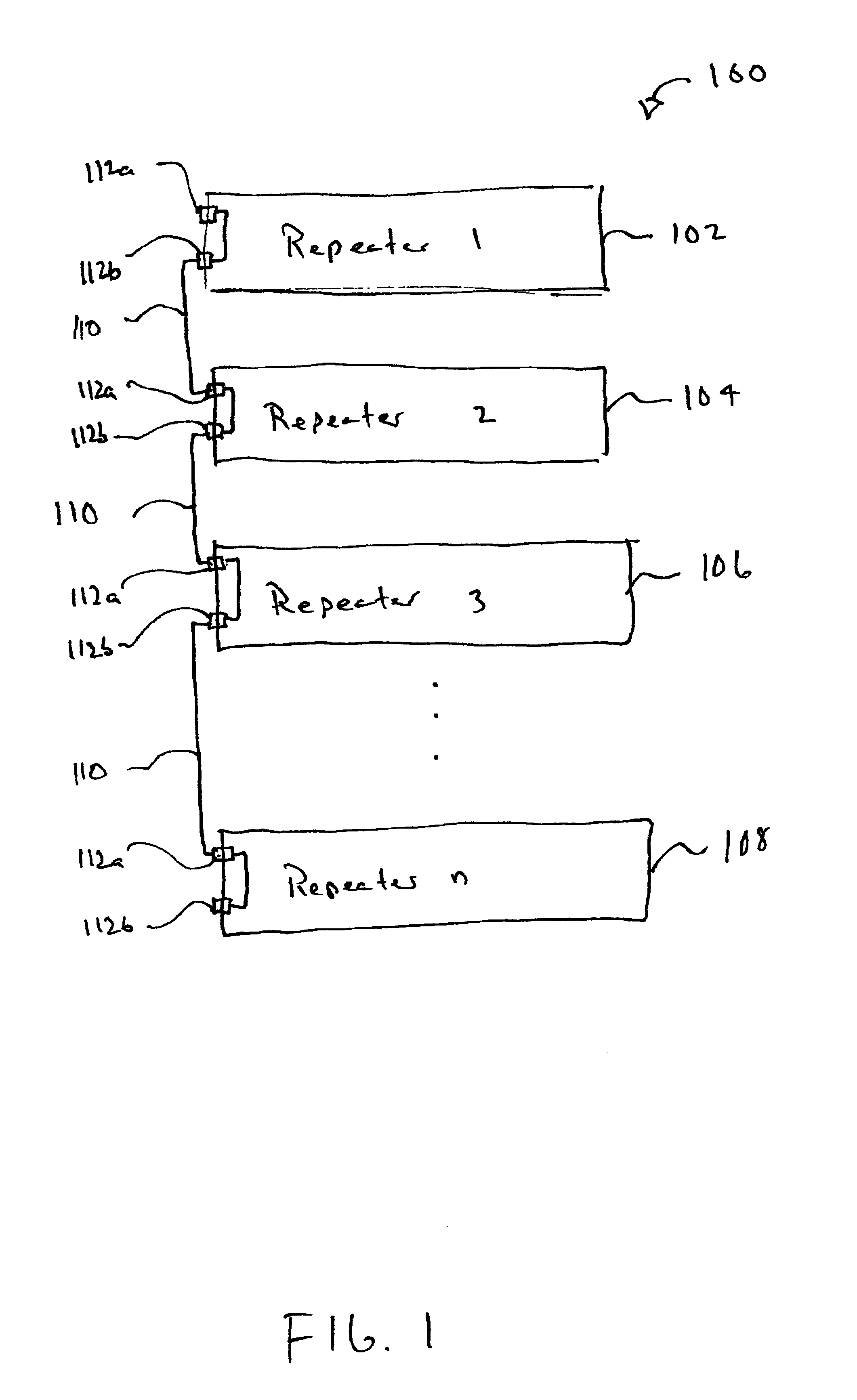
[0033]Referring to FIG. 1, a plurality of repeaters are connected into the same collision domain via stacking bus architecture in accordance with the preferred embodiment of the present invention. In particular, system 100 includes a first repeater 102, a second repeater 104, a third repeater 106 and an unlimited number of repeaters up to and including repeater n 108.

[0034]Each repeater 102 through 108 may be a commercially available repeater (sometimes referred to as a hub) that is appropriately outfitted and configured to perform according to the appropriate standards (e.g., IEEE 802.3, etc.), repeat signals via its physical ports, to detect collisions across its ports and send corresponding collision signals, and may also be outfitted with appropriate hardware and software to perform various function...


PUM


Abstract

A system for connecting multiple repeaters into a single collision domain comprising a first repeater, a second repeater and a stacking bus. The first repeater has a plurality of network ports. The second repeater also has a plurality of network ports. The stacking bus connects the first repeater and the second repeater and is configured to relay status signals between the first and said second repeaters.

Description

PRIORITY CLAIM[0001]This application is a continuation-in-part of, and claims priority to, co-owned, U.S. patent application Ser. No. “09 / 416,365”, entitled “METHODS AND CIRCUITS FOR STACKING BUS ARCHITECTURE” filed on Oct. 8, 1999 now abandoned, which itself claims priority to Provisional Application Ser. No. 60 / 103,813 filed Oct. 8, 1998, entitled “THE STRUCTURE OF STACKING BUS USING IN TRex8-R”. The contents of these earlier filed applications are hereby incorporated by reference.BACKGROUND OF THE INVENTION[0002]1. Field of the Invention[0003]The present invention relates to network devices, circuitry, and architecture. More particularly, the present invention relates to repeater circuits and stacking bus architectures used within 10 MB or 100 MB Ethernet other computer data networks.[0004]2. Description of the Prior Art[0005]Ethernet is an example of a well-known and popular standard for facilitating communication between devices and machines within information networks. Data ne...

Claims


Application Information

Patent Timeline
Patent Type & Authority Patents(United States)
IPC IPC(8): G06F13/40H04L12/56H04L12/46
CPCG06F13/4095H04L12/46H04L49/351H04L49/3027
Inventor CHEN, XICHANG, BRIAN
Owner AVAGO TECH INT SALES PTE LTD
Why Eureka
Try Eureka