Lower structure of vehicle front pillars

a technology for front pillars and lower structures, which is applied in the direction of roofs, transportation and packaging, vehicle arrangements, etc., can solve the problems of inferior molding performance of the vehicle side components, difficulty in ensuring sufficient rigidity of the front pillars while opening and closing doors, and general versatility of the door hinges, so as to improve workability, enhance the performance of the outer panel of the side body and the outer reinforcement of the front pillars, and reduce weight and cost

Inactive Publication Date: 2010-11-25
SUZUKI MOTOR CORP
View PDF10 Cites 21 Cited by
  • Summary
  • Abstract
  • Description
  • Claims
  • Application Information

AI Technical Summary

Benefits of technology

[0019]In the invention according to the sixth aspect, each of the outer panel for the side body and the outer reinforcement for the front pillar is not formed in a bag shape extending down to the lower end of the side sill. Alternatively, the outer panel for the side body and the outer reinforcement for the front pillar, have lower edges which may be aligned on a substantial center, in the vertical direction, of the side sill. Therefore, the molding performance of each of the outer panel for the side body and the outer reinforcement for the front pillar, can be enhanced, and furthermore operation for coating their aligned end portions with a sealer, can be made simpler, so that the workability can be enhanced.
[0020]In addition, since the outer panel for the side body is not formed to extend down to the lower end of the side sill, weight and cost can be reduced. Furthermore, since the outer reinforcement for the side sill is arranged in an outermost surface of the vehicle, it is possible to form a large transverse cross section of the outer reinforcement for the side sill, so that the rigidity thereof increases.

Problems solved by technology

However, the structure proposed in “JP 10-007020 A” has the following problems.
Specifically, since the structure in which the bead is provided to the door hinge is for absorbing impacts, it is difficult to secure sufficient rigidity of the front pillars while opening and closing the doors.
Since the shape of the door hinge is unusual, the general versatility of the door hinge is inferior.
Furthermore, since the bead is formed in multiple positions, the molding performance of the vehicle side component is inferior.
Specifically, it is difficult for the lower portion of the front pillar to absorb the impact applied to the vehicle body via wheels during a vehicle collision, and furthermore, the molding performance of the front pillar outer reinforcement is inferior.
Therefore, operations for sealing panel ends become complex.

Method used


Image

  • Lower structure of vehicle front pillars
  • Lower structure of vehicle front pillars
  • Lower structure of vehicle front pillars

Examples


Embodiment Construction

[0031]Hereinafter, an embodiment of the present invention will be described with reference to the accompanying drawings.

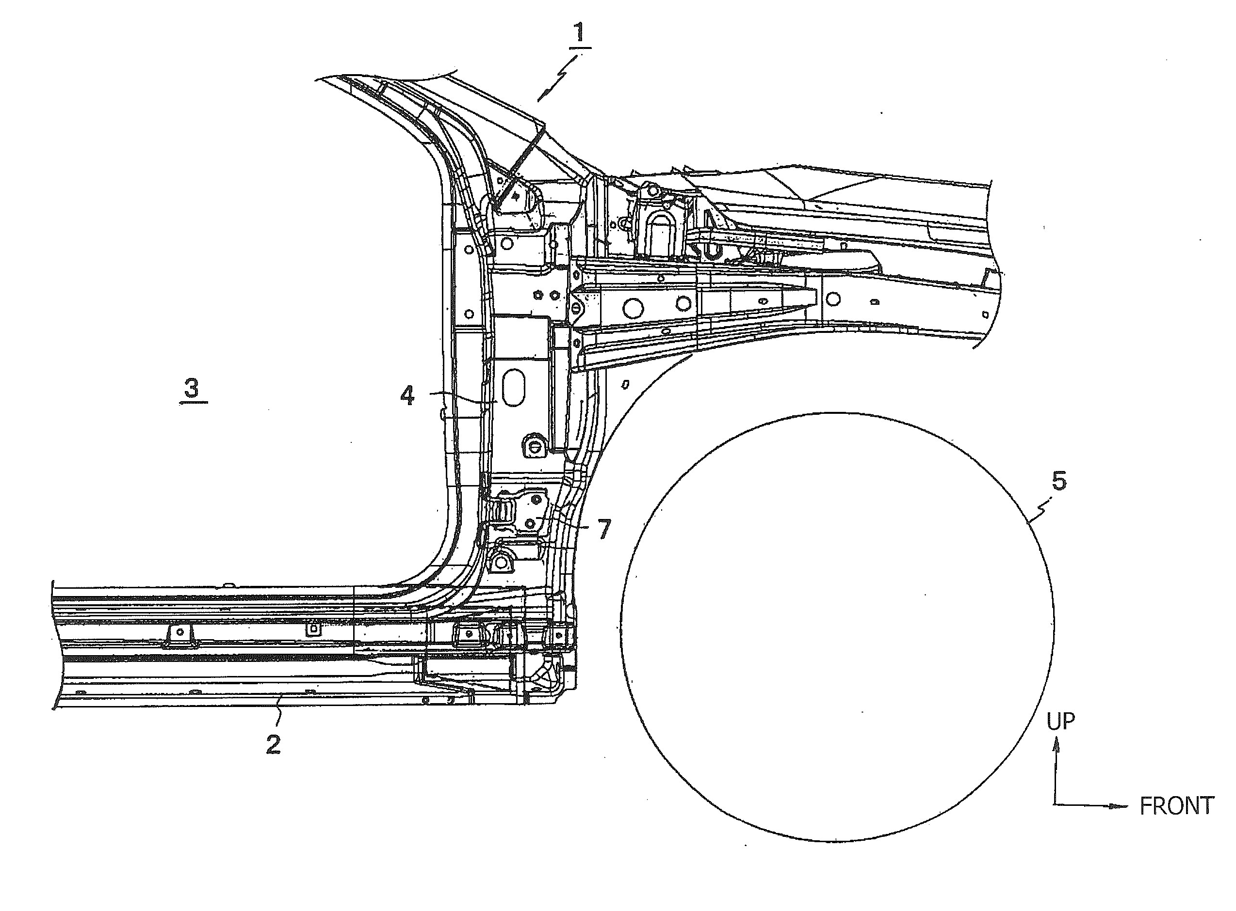
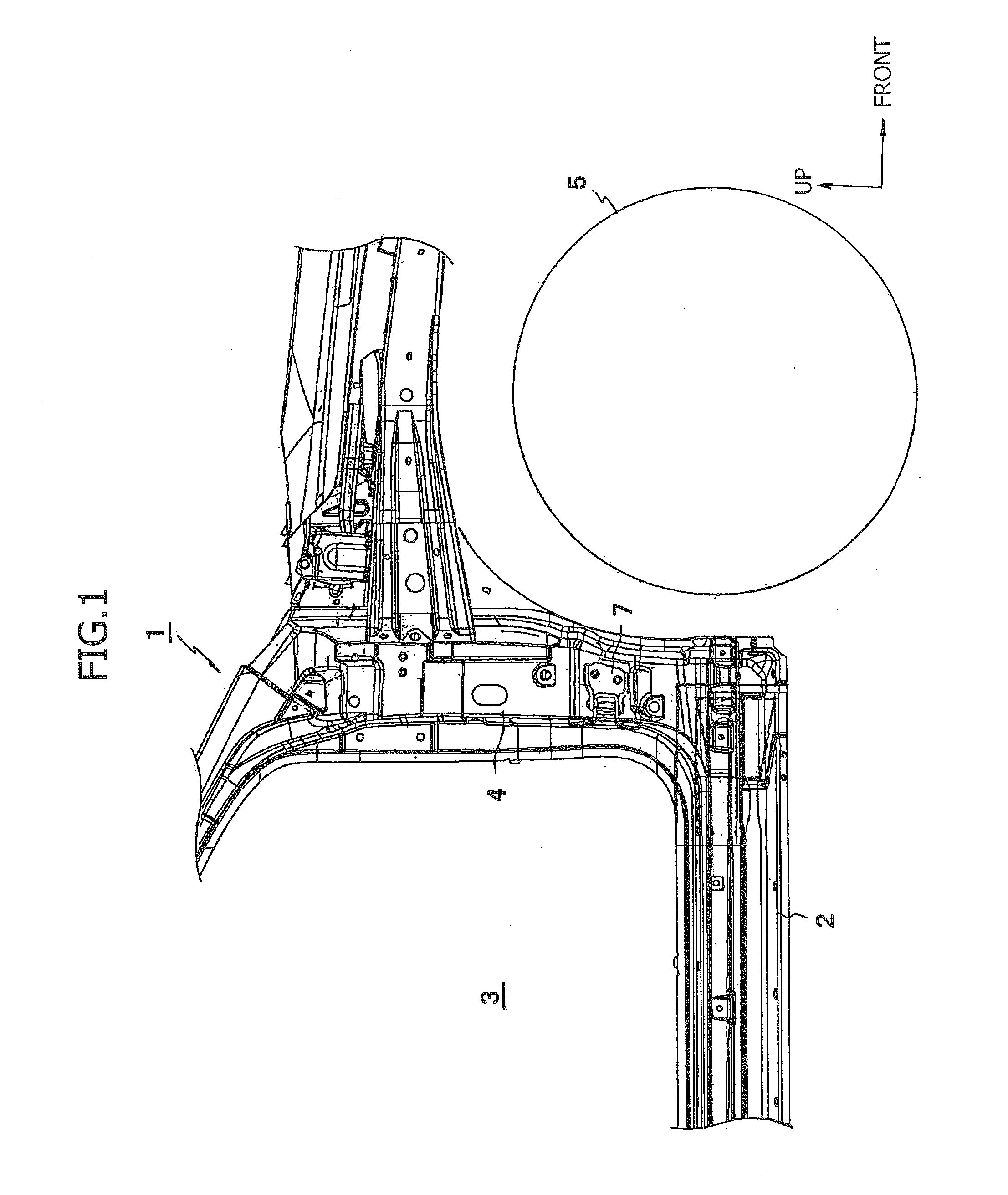
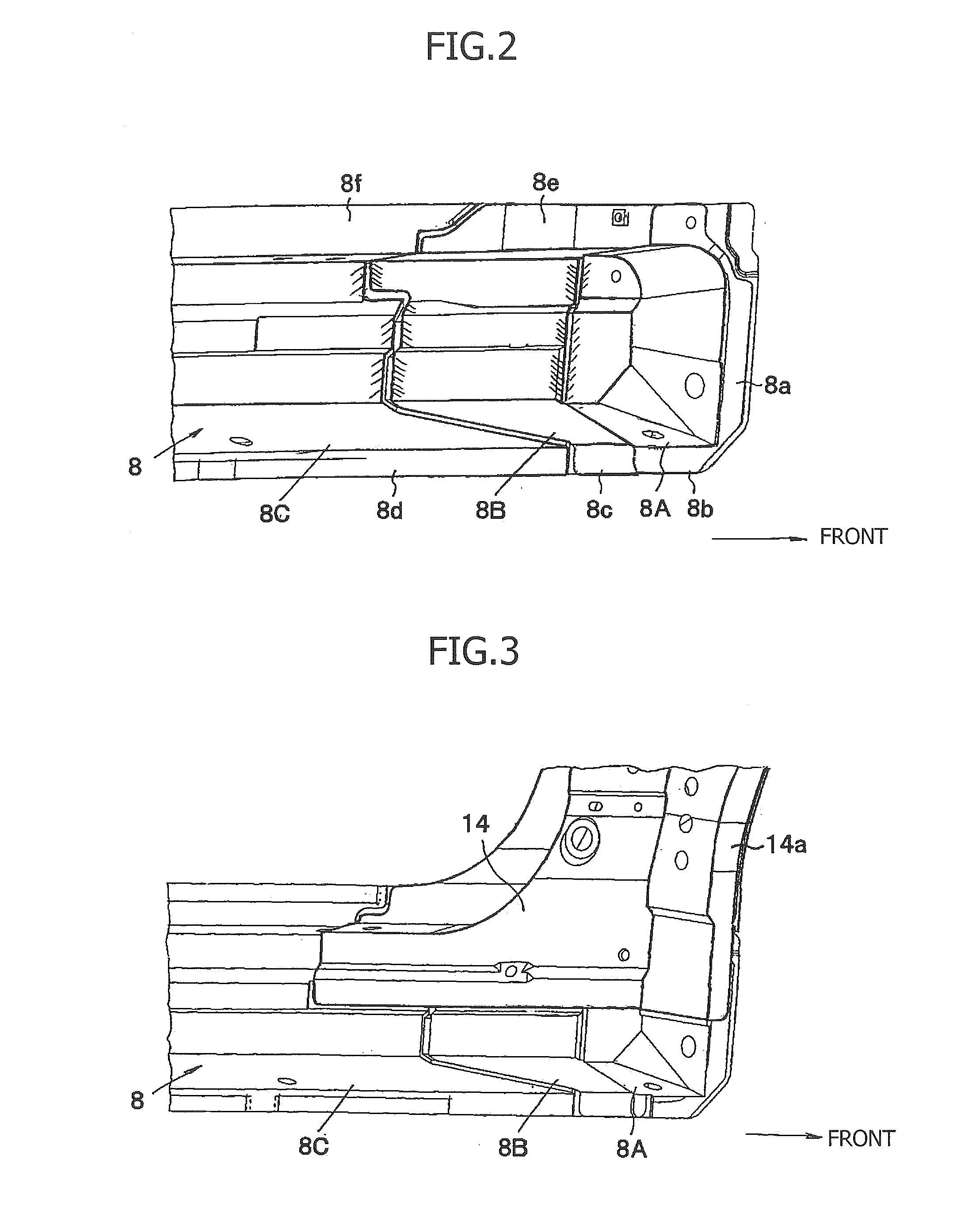
[0032]FIG. 1 is a side view of a front portion of a vehicle showing a lower structure of a front pillar according to the present invention. FIG. 2 is a partial perspective view showing a three segment structure of an outer reinforcement for a side sill. FIG. 3 is a partial perspective view showing a state in which an outer reinforcement for the front pillar is mounted on the outer reinforcement for the side sill shown in FIG. 2. FIG. 4 is a partial perspective view showing a state in which an outer panel for a side body is mounted on the outer reinforcement for the front pillar and the outer reinforcement for the side sill shown in FIG. 3. FIG. 5 is a partial side view of a lower portion of the front pillar. FIG. 6 is a partial side view of the lower portion of the front pillar as seen from a vehicle compartment side. FIG. 7 is a cross sectional view taken along th...


PUM


Abstract

In lower structures for vehicle front pillars, there are paired right and left side sills arranged in lower portions on both sides of a vehicle, respectively; an outer portion, in a vehicle width direction, of each side sill is formed of an outer reinforcement for a side sill; a inner panel for the side sill is arranged on an inner side, in the vehicle width direction, of each side sill; the front pillars are formed so as to stand on front ends of the side sills, respectively; outer panels for side bodies cover outer reinforcements for the respective front pillars and parts of the respective side sills; each outer reinforcement for side sill is segmented, in the vehicle front and rear direction, into three parts, that is to say, first to third components positioning sequentially from a front of the vehicle; strengths of the first to third components are set to be higher sequentially in this order; and the first, second, and third components are joined and integrated together.

Description

CROSS-REFERENCE TO RELATED APPLICATIONS[0001]This application claims the benefit of the filing date of Japanese Patent Application No. 2009-120556 filed May 19, 2009, the entire disclosure of which is hereby incorporated herein by reference.FIELD OF THE INVENTION[0002]The present invention relates to a lower structure of vehicle front pillars in which lower portions of the front pillars can absorb an impact applied to a vehicle body via the wheels during a vehicle collision.BACKGROUND OF THE INVENTION[0003]“JP 10-007020A” proposes lower vehicle body structure in which lower portions of front pillars can absorb an impact applied to a vehicle body via wheels during a collision, even if the vehicle body structure does not allow lower end portions of the front pillars to project toward the front of the vehicle. In the structure, a mounting portion of a lower door hinge, which mounts to the front pillar, is attached to a lower part of an outer sidewall portion in the vehicle width direct...

Claims


Application Information

Patent Timeline
Patent Type & Authority Applications(United States)
IPC IPC(8): B62D25/04
CPCB62D25/02B62D25/04B62D25/025
Inventor ITAKURA, AKIRA
Owner SUZUKI MOTOR CORP
Why Eureka
Try Eureka