Chamber for a freeze-drying device

a technology of chambers and freezers, which is applied in the direction of drying solid materials, drying, lighting and heating apparatus, etc., can solve the problems of product quality loss, insufficient accuracy in maintaining uniform water vapor partial pressure in the chamber, and insufficient uniformity of ice temperature that develops

Inactive Publication Date: 2005-07-26
STERIS GMBH
View PDF8 Cites 22 Cited by
  • Summary
  • Abstract
  • Description
  • Claims
  • Application Information

AI Technical Summary

Problems solved by technology

The desired prerequisite that a uniform water vapor partial pressure be maintained in the chamber is no longer met with sufficient accuracy; the ice temperature that develops is no longer uniform.
Product quality losses are the resulting consequence.
These measures, however, have had only limited success because the differences in temperature between the rim and the storage surfaces are about 20° C.
These measures, however, are associated with practically unsolvable technical difficulties and economic disadvantages.
Said masses would have to be cooled down to −40° C. and often even down to −60° C. during the freezing process, which leads either to an impermissibly long freezing time or to separate cooling systems, which have to achieve a multiple of the cooling output that is required for the storage plates and the product.
Apart from these economic problems, it is technically difficult to cool the flanges on the chamber and the flange on the door to e.g. −50° C. The seals between the chamber and the door must remain functional at low temperatures, and it is difficult to avoid water vapor condensation on said flanges.
Insulating the flange against water vapor condensation is technically not possible because the chamber flange and the door are located in sterile rooms.

Method used


Image

  • Chamber for a freeze-drying device
  • Chamber for a freeze-drying device

Examples


Embodiment Construction

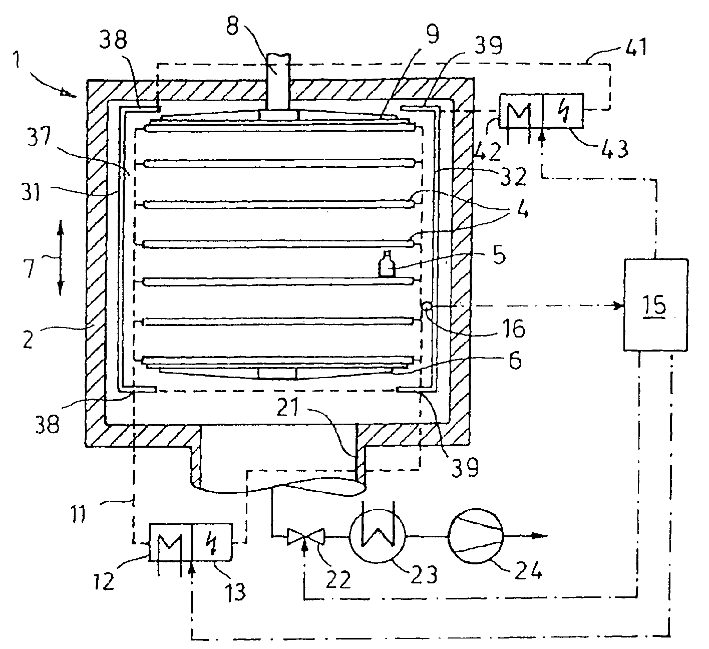
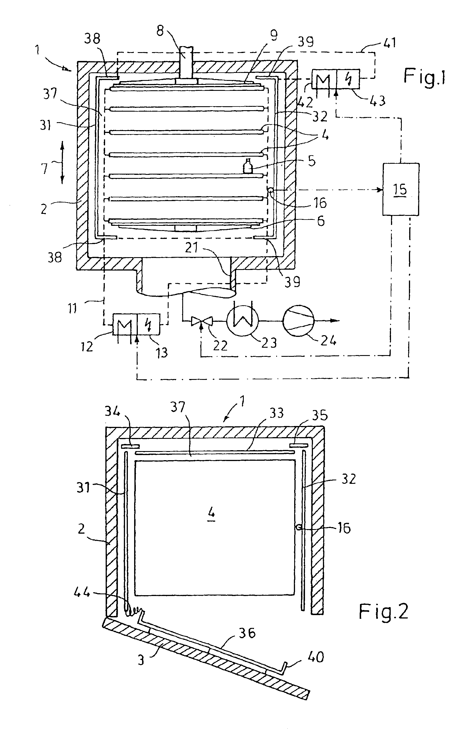
[0012]In the drawings, a freeze-drying device includes a chamber 1, having a chamber wall 2, a door 3 (FIG. 2), and storage plates 4 that are located in chamber 1. An exemplary bottle 5 is shown in the drawings placed onto a storage plate 4. The lower storage plate 4 is supported by a stationary base plate 6. The remaining storage plates 4 can be displaced back and forth (double arrow 7) such that their distance can be modified. By sliding the storage plates 4, e.g. with the help of a hydraulic drive (piston rod 8), the bottle 5 is closed in the known fashion with stoppers. The stoppers that are placed onto the bottles 5 before starting the freeze-drying process, contain laterally ending through-channels for the water vapor. The uppermost storage plate 4 is attached to the platen 9 of the piston rod 8.

[0013]The storage plates 4 are part of a temperature-adjusting system 11, indicated with dotted lines. A brine flows through it, which is cooled with a heat exchanger 12 (connected to ...


PUM


Abstract

A chamber for a freeze-drying device with storage surfaces, whose temperature can be regulated, for containers containing the product that is to be freeze-dried. The chamber includes an optical shield comprised of shield components, whose temperature can be regulated. The shield is positioned between the storage surfaces and the interior wall surfaces of the chamber.

Description

FIELD OF THE INVENTION[0001]The invention relates to a chamber for a freeze-drying device with storage surfaces whose temperature can be regulated for containers that carry the product that is to be freeze-dried.BACKGROUND OF THE INVENTION[0002]Freeze-drying has gained ground especially in the pharmaceutical industry for the preservation of medications, vaccines etc. In the chambers of modern freeze-drying devices, a plurality of storage plates are located, the storage plates having storage surfaces that can accommodate a multitude of containers, bottles or the like (100,000 or more). The product, which is generally dissolved in water, is filled into containers of this type. Before starting the freeze-drying process, the liquid is frozen. This step generally already occurs in the chamber of the freeze-drying unit by cooling the storage surfaces to an accordingly low temperature (−40° C. to −60° C.).[0003]German disclosure document 197 19 298 (U.S. Pat. No. 6,163,979 to Oetjen et al....

Claims


Application Information

Patent Timeline
Patent Type & Authority Patents(United States)
IPC IPC(8): F26B5/04F26B5/06F26B9/06
CPCF26B5/06
Inventor HASELEY, PETEROETJEN, GEORG-WILHEIM
Owner STERIS GMBH
Why Eureka
Try Eureka