
Impact sound insulation

a sound insulation and impact technology, applied in the field of sound insulation materials, can solve the problems of increasing the thickness of the material, affecting the sound insulation effect, so as to reduce the height required and prevent damage

Inactive Publication Date: 2005-07-26
ECORE INT
View PDF20 Cites 79 Cited by
  • Summary
  • Abstract
  • Description
  • Claims
  • Application Information

AI Technical Summary

Benefits of technology

[0006]An object of the present invention is to provide an insulating material for use with decorative flooring tile and the like which minimizes the height required. Another object of the invention is to provide an insulating material which has the acoustic properties and the strength characteristics required to be used in a flooring system.
[0007]These and other objects are accomplished by the flooring system described herein. The flooring system has a subfloor, a decorative top layer, and a substrate provided therebetween. The substrate has a top surface and an oppositely facing bottom surface. The bottom surface positioned proximate the subfloor and the top surface is positioned proximate the decorative top layer. Voids are provided in the substrate which extend between the top surface and the bottom surface. The substrate is manufactured from rubber in sheets which are cut to the desired configuration. The substrate has the strength characteristics to support the decorative layer and prevent damage thereto and the sound dampening characteristics to provide decibel reduction through the substrate.
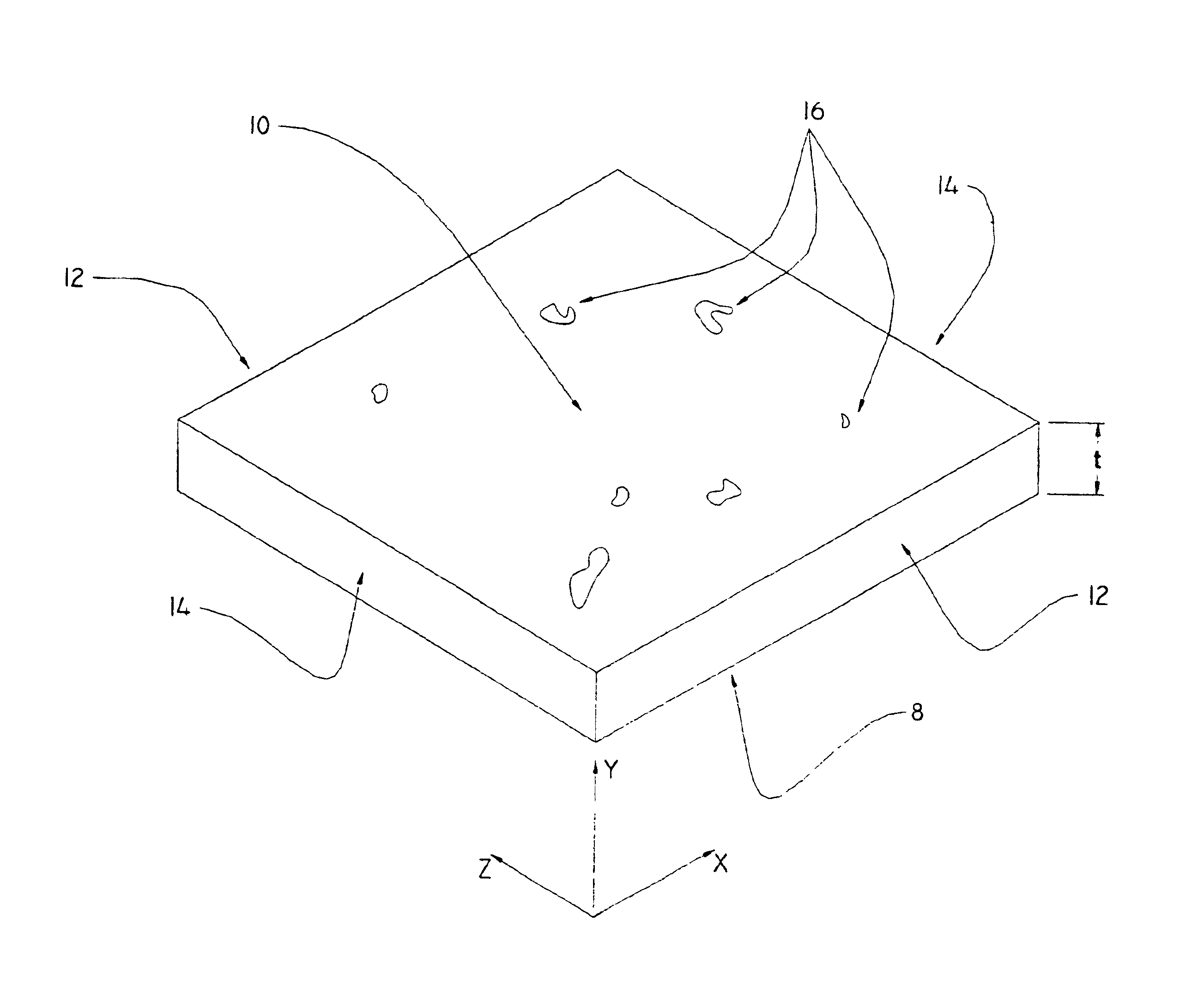
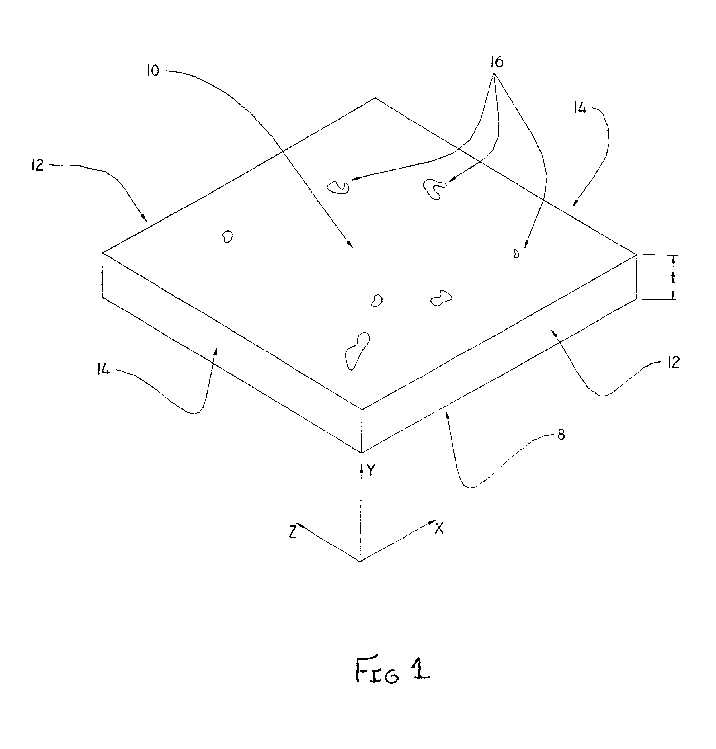
[0008]The invention is also directed to a substrate for use in a flooring system which has a subfloor and a decorative upper layer. The substrate is made in a sheet which has a bottom surface, a top surface, side surfaces and end surfaces. The top surface and the oppositely facing bottom surface are essentially parallel to each other and are spaced apart by the thickness of the substrate. Voids are provided in the substrate, the voids are provided between particles of rubber or other similar material. When the substrate is positioned between the subfloor and the decorative top layer, the particles of rubber provide the strength required to prevent deformation of the substrate in the direction of the thickness and the voids contribute to the sound dampening characteristics required to provide decibel reduction across the thickness of the substrate.

Problems solved by technology

However, despite their numerous desirable qualities, these materials typically exhibit poor acoustic properties.
Poor sound or acoustic properties are extremely undesirable in all structure, but in particular in high-rise buildings which are used as office buildings, hotels, apartments, and the like.
While the insulating material of the prior art dampens the impact sound transmission, several disadvantages have been associated with the use of the insulating material.
All of these have problems associated therewith.
Increased thickness associated with these materials is a significant problem.
Moreover, the increased thickness of the floor increases the overall height required for the building, thereby significantly increasing the cost of materials and construction.
Additionally, as many of the materials are designed to reduce impact sound, the structural stability of the material is weak.
Without the support, the tiles would crack and deform as pressure is applied.
The introduction of the support layer further adds to the height requirements, resulting in greater expense.

Method used


Image

  • Impact sound insulation
  • Impact sound insulation
  • Impact sound insulation

Examples


Embodiment Construction

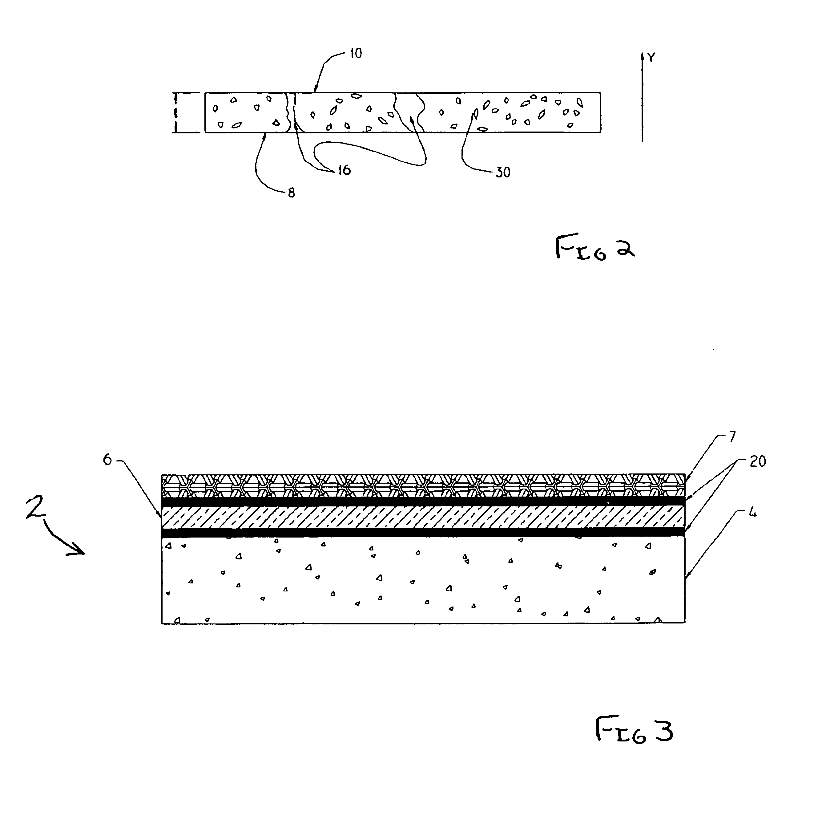
[0012]Referring to FIG. 3, a flooring system 2 according to the present invention is shown. The flooring system 2 has a base or subfloor 4. The subfloor 4 is an integral part of the building or structure and can be in the form of a concrete slab, plywood floor, or any other known material commonly used in the building industry. Positioned above the subfloor is a sound absorbing substrate 6 and decorative top layer 7. The sound absorbing substrate 6 may be affixed to the subfloor 4 and / or the decorative top layer 7 by means of mastic or glue layers 20. As the use of mastics or glues are well known in the industry, a further explanation of the glue will not be provided.

[0013]The decorative top layer may be wood, linoleum, ceramic tile, carpet, or any other known flooring. Individual components of the decorative top layer 7 are positioned in place and secured to each other by frictional engagement, glue, grout, or other conventional means. As decorative flooring is commonly used, a fur...


PUM

PropertyMeasurementUnit
thicknessaaaaaaaaaa
thicknessaaaaaaaaaa
heightaaaaaaaaaa

Abstract

A substrate for use in a flooring system which has a subfloor and a decorative upper layer. The substrate is made in a continuous sheet which has a bottom surface, a top surface, side surfaces and end surfaces. The top surface and the oppositely facing bottom surface are essentially parallel to each other and are spaced apart by the thickness of the substrate. Voids are provided in the substrate, the voids are provided between particles of rubber or other similar material. When the substrate is positioned between the subfloor and the decorative top layer, the particles of rubber provide the strength required to prevent deformation of the substrate in the direction of the thickness and the voids contribute to the sound dampening characteristics required to provide decibel reduction across the thickness of the substrate.

Description

FIELD OF THE INVENTION[0001]The invention is directed to sound insulating material for use in flooring. In particular, a sound insulating material which exhibits the strength characteristics required to properly support the decorative top layer of the flooring.BACKGROUND OF THE INVENTION[0002]Ceramic, masonry, and wood tiles have been used for many years in the construction industry. These materials are used for many reasons including strength, durability, and appearance. However, despite their numerous desirable qualities, these materials typically exhibit poor acoustic properties. Poor sound or acoustic properties are extremely undesirable in all structure, but in particular in high-rise buildings which are used as office buildings, hotels, apartments, and the like. As the occupants of one floor do not want to be disturbed from the occupants of the floor above, it is typical to add insulating material between the subfloor and the decorative tiles. In fact, standards have been deve...

Claims


Application Information

Patent Timeline
Patent Type & Authority Patents(United States)
IPC IPC(8): A63C19/00A63C19/04E04F15/20
CPCA63C19/04E04F15/20Y10T428/31826E04F15/206
Inventor DOWNEY, PAUL CHARLES
Owner ECORE INT
Learn More