Terminal Reversing Block

a technology of reversing blocks and terminals, which is applied in the direction of protective switch terminals/connections, coupling device connections, protective switch details, etc., can solve the problems of increasing the cost of arcs and the space required to bend cables in reversing arcs, so as to minimize the length and width, the effect of minimizing the height required

Active Publication Date: 2011-06-23
BOLTSWITCH
View PDF8 Cites 5 Cited by
  • Summary
  • Abstract
  • Description
  • Claims
  • Application Information

AI Technical Summary

Benefits of technology

[0010]The terminal reversing block's housing can be sized and shaped to fit above or below the electrical disconnect device. The terminal reversing block is preferably sized and shaped to have the same or roughly the same length and width as the electrical disconnect device, thereby minimizing the length and width required for the completed assembly of the terminal reversing block and electrical disconnect device. The body portion of the terminal may include an offset section that separates the longitudinal axes of the mating portion and connecting portions thereby providing easy access to the terminal collars on the electrical disconnect device and the terminal reversing block. Alternatively, the terminal reversing block can be sized and shaped to extend out from at least one side of the electrical disconnect device so as not to increase the height of the electrical disconnect device, thereby minimizing the height required for the enclosure of the terminal reversing block and electrical disconnect device.

Problems solved by technology

Consequently, if a linear, single-direction arrangement of the cables is unworkable in a particular situation large spaces are required to bend an electrical input or output cable around to effect a variation in a cable's direction.
This may be due to limitations on space in the enclosure that contains the electrical disconnect device.
This means the space required to bend the cables in a reversing arc may be larger than is available.
In addition, the extra lengths of cables or cables required to make such an arc increases the cost.

Method used


Image

  • Terminal Reversing Block
  • Terminal Reversing Block
  • Terminal Reversing Block

Examples


Embodiment Construction

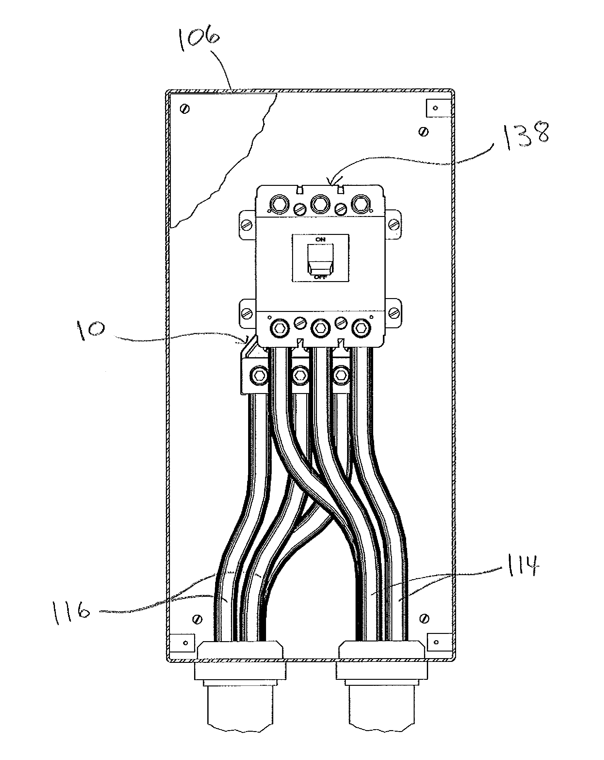
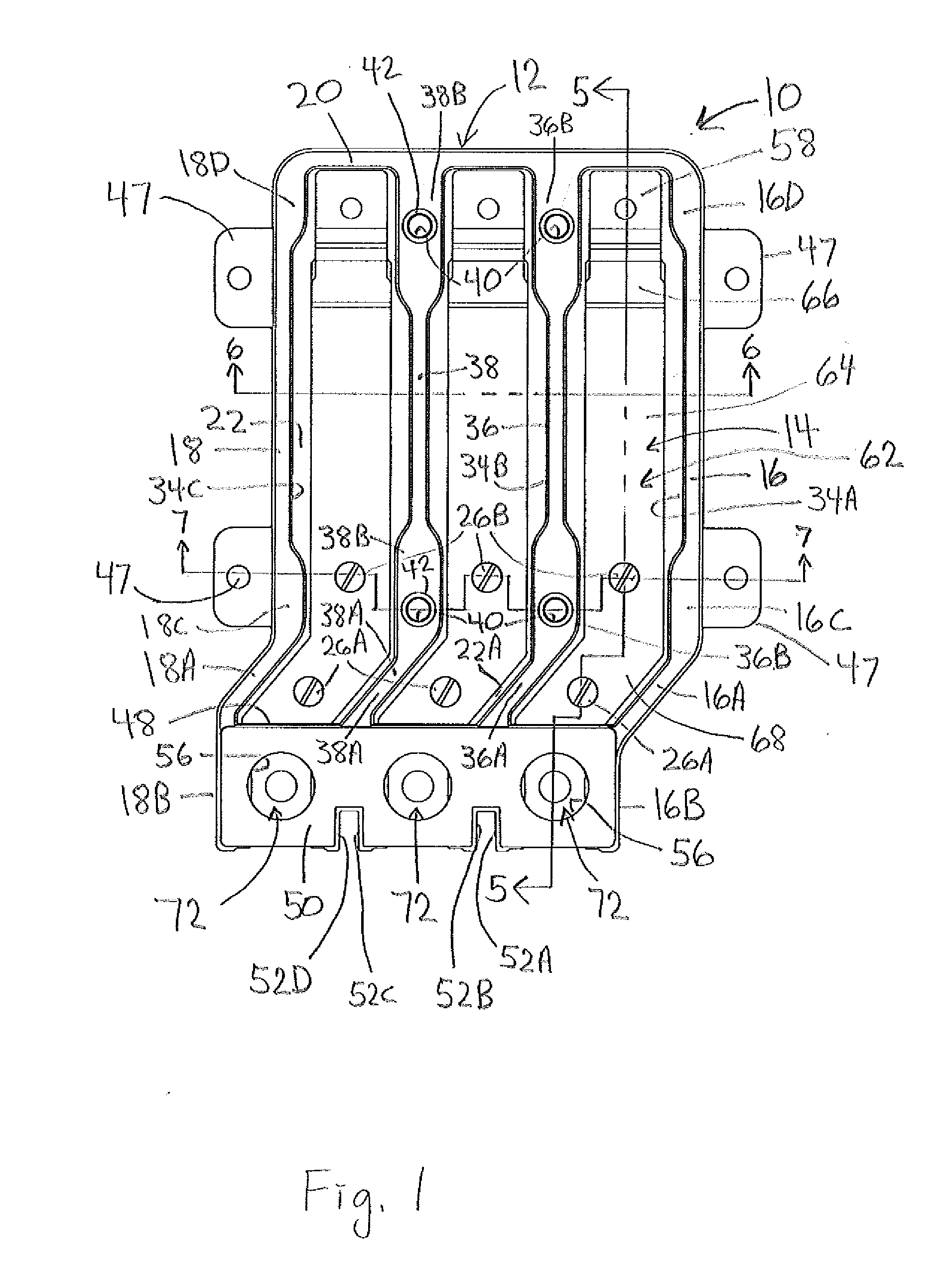
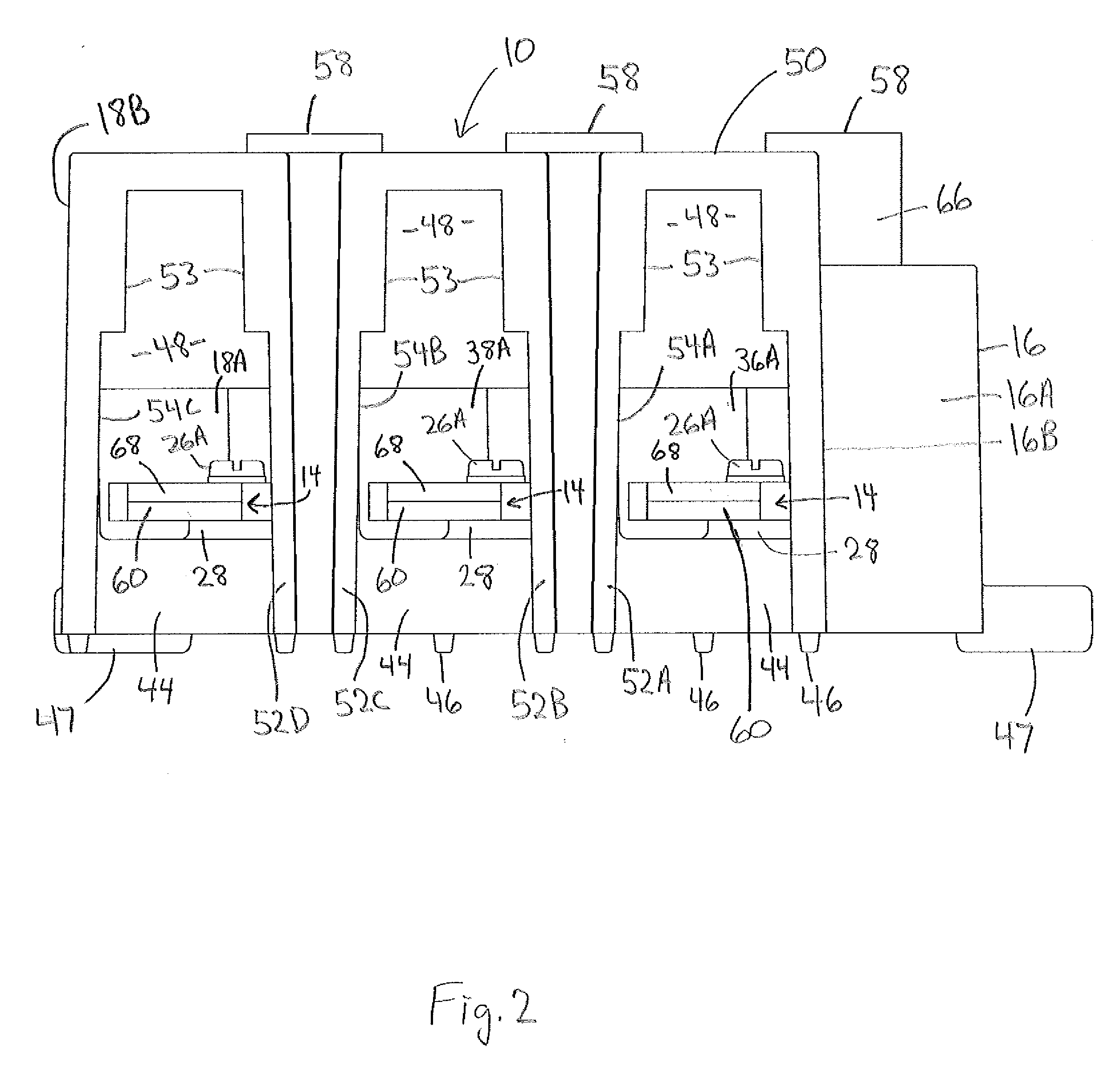
[0033]A terminal reversing block 10 in accordance with the present invention is shown in FIG. 1. Terminal reversing block 10 is adapted for heavy duty power transmission applications. For example and not by way of limitation, the illustrated terminal reversing block 10 is rated at 240 volts AC / 125 volts DC and 400 amps. Terminal reversing block includes three main components, a housing or base 12, one or more terminals or blades 14, and a terminal collar 72 associated with each terminal. For clarity in illustrating the housing 12 and terminals 14, the terminal collars 72 are not shown in FIGS. 2-7. The terminal collars are shown and described below in connection with FIGS. 11 and 14. Also, references herein to front, side, top, bottom and the like are from the point of view of a terminal reversing block mounted on a horizontal surface. Obviously the terminal reversing block could be mounted on a vertical surface such as a wall or a rack. Accordingly, directional references to the bl...


PUM


Abstract

A terminal reversing block mounts to a standard electrical disconnect device such as a circuit breaker or a pullout switch. The disconnect device has a housing which defines a cavity that faces in one direction for receiving a cable. Front and rear contacts are in the housing, one of which extends into the cavity for engagement with a cable. A terminal reversing block has a housing with at least one pocket which faces in a direction other than the opposite of the direction in which the disconnect device's cavity faces. A terminal collar disposed in the terminal reversing block pocket is engageable with a cable inserted into the pocket. A terminal in the reversing block has a mating portion and a connecting portion. The connecting portion engages the terminal collar. The mating portion engages one of the front and rear contacts of the electrical disconnect device. The arrangement of the directions in which the cavity and pocket face permits routing of the cables to minimize space requirements in a confined area, such as an enclosure or a cabinet.

Description

CROSS REFERENCE TO RELATED APPLICATION[0001]This application claims the benefit of U.S. Provisional Application Ser. No. 61 / 288,805, filed Dec. 21, 2009, the disclosure of which is incorporated by reference herein.BACKGROUND OF THE INVENTION[0002]The present invention relates to adapters for rerouting electrical wires or cables. In particular, the present invention relates to terminal reversing blocks for changing the direction of electrical cables extending out of an electrical disconnect device. As used herein the term “cable” will be used to describe electrical conductors including wires, cables, busbars or other conductors.[0003]High current electrical disconnect devices, such as pull-out switches or circuit breakers for example, are typically connected to thick, heavy electrical cables. The cable connectors of such disconnect devices are commonly referred to as terminal collars. The terminal collars conventionally are located on opposite sides of the housing of the disconnect d...

Claims


Application Information

Patent Timeline
Patent Type & Authority Applications(United States)
IPC IPC(8): H01R33/96H01R9/00H01H33/02
CPCH01H11/0031H01R9/24H01H71/08H01H71/0264
Inventor ERICKSON, JOHN W.ERICKSON, JAMES A.ERICKSON, JOHN WALTER
Owner BOLTSWITCH
Why Eureka
Try Eureka