Folding device as room divider or room closure

a technology for dividers and rooms, applied in the field of folding devices, can solve the problems of increasing the view obstruction, the view obstruction portion is undetectable, and the view obstruction is increased by architects and planners as well as consumers and users

Inactive Publication Date: 2005-07-26
SOLARLUX ALUMINUM SYST
View PDF5 Cites 4 Cited by
  • Summary
  • Abstract
  • Description
  • Claims
  • Application Information

AI Technical Summary

Benefits of technology

[0007]It is an object of the present invention to configure a folding device of the aforementioned kind such that it provides a constructively light visual appearance with a minimal view obstructing portion.
[0009]The configuration of the guide elements provided on the free wing edges of the opening wing or opening wings comprising a hinge having at its free side a holding element and including covering of the intermediate space between the holding elements by means of the profiled strip connected fixedly at least to the opening wing, enables elimination of the conventionally used post. The connection of the free wing edge of the opening wing is realized simply by means of the holding elements which can be configured without problems and without any loss of stability with a very minimal height. The laterally projecting width of the holding elements can also be much smaller than that of the conventionally employed posts so that, even with the profiled strip connected to the opening wing, a significantly reduced view obstructing portion results. Since the profiled strip upon opening of the wings pivots together with the opening wing, the view obstructing portion or width is further reduced in the open state of the folding device.

Problems solved by technology

However, the posts which have been used in the past increase the view obstructing portion of the vertical profiles at this location; this is not desired by architects and planners as well as consumers and users.
In particular, when two opening wings of wing pairs meet one another, the view obstructing portion is undesirably large because of the two additional posts.

Method used


Image

  • Folding device as room divider or room closure
  • Folding device as room divider or room closure
  • Folding device as room divider or room closure

Examples


Embodiment Construction

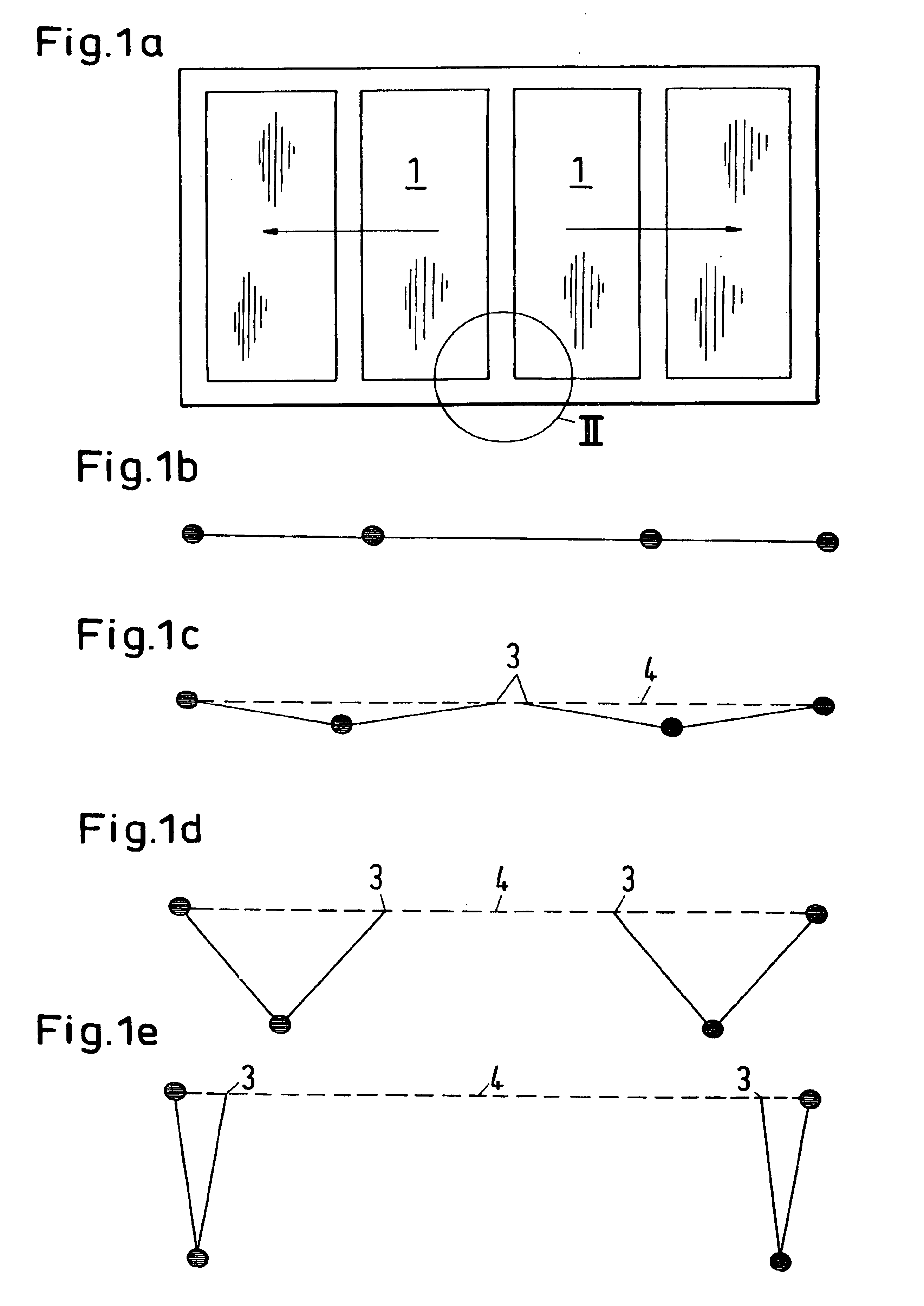
[0023]FIG. 1a shows a four-wing folding device with two wing pairs. Opening of this device is illustrated in pictograms in FIGS. 1b through 1e. The two free wing edges 3 of the opening wing 1 always remain in the plane 4 defined by the guide rails (not illustrated); this plane is indicated by dashed lines.

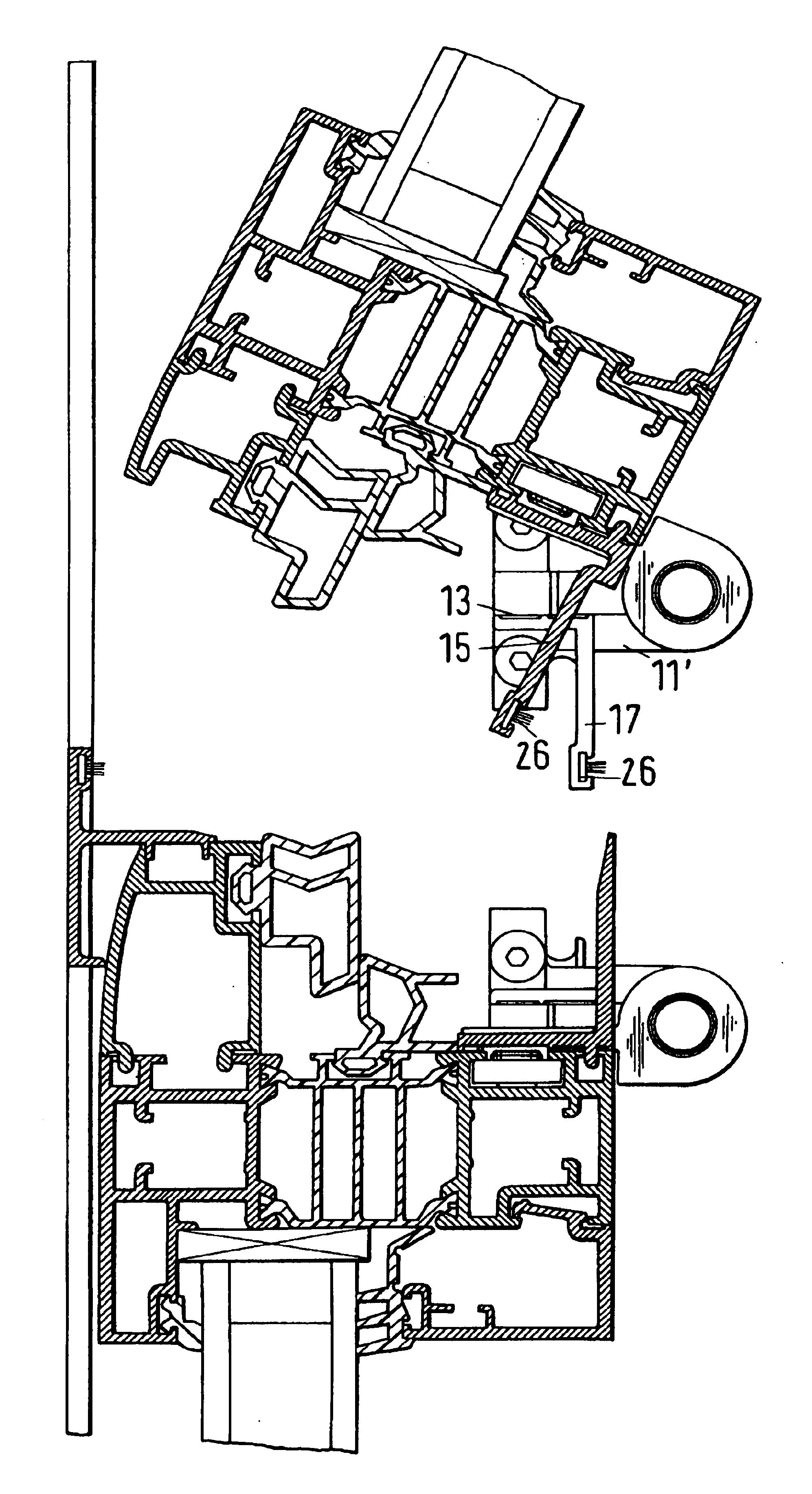
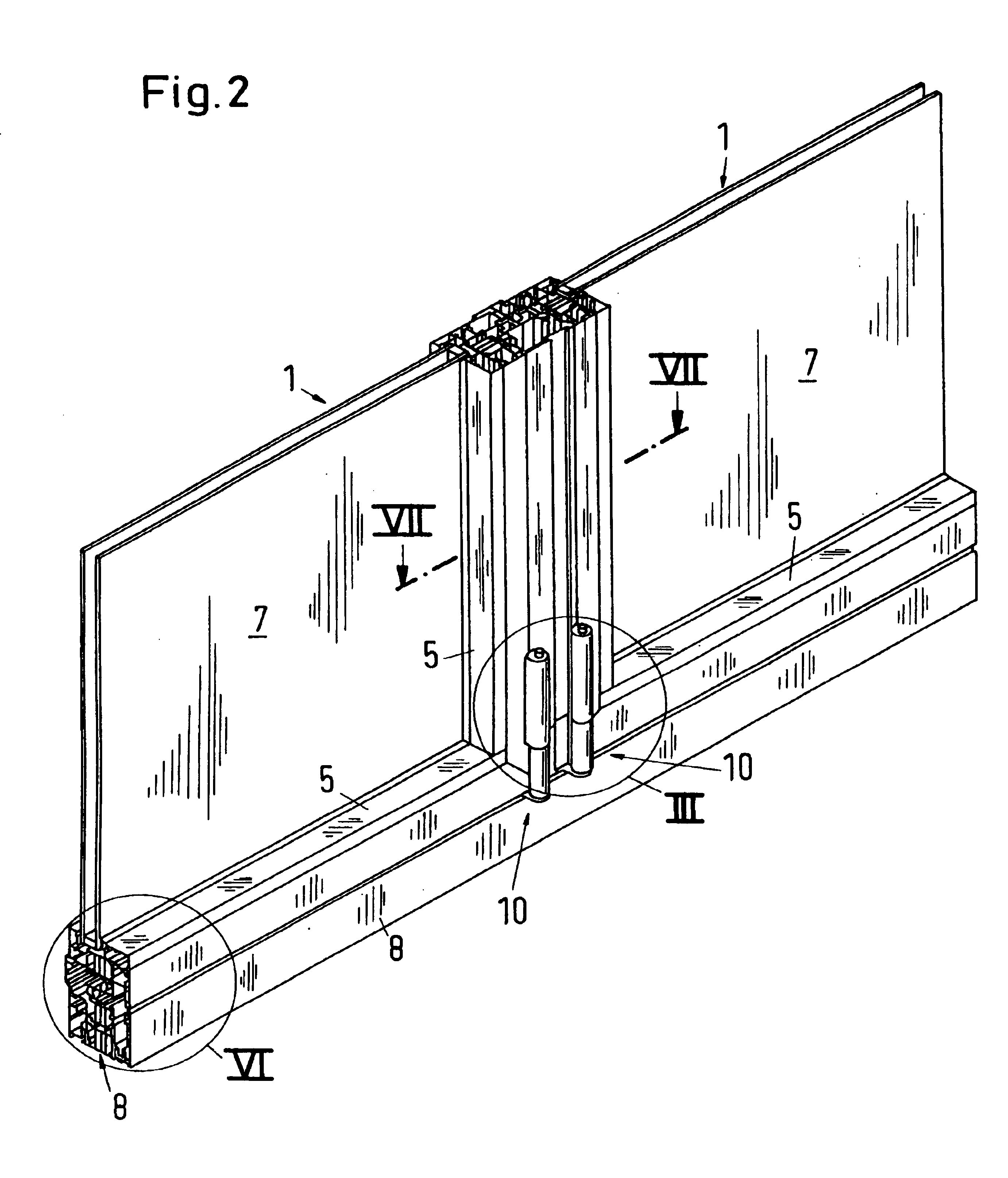
[0024]FIG. 2 shows the lower central area of the abutting two free edges of the opening wings 1 of the folding device. The opening wings 1 of the folding device in the illustrated embodiment open inwardly relative to the position of the viewer of FIG. 2. The opening wings 1 are comprised of double pane panels 7 framed in wing frames 5. The wings are slidably guided at the top and bottom in guide rails 8 by means of guide elements. The embodiments are illustrated in more detail in the following Figures.

[0025]The configuration according to the Invention is best illustrated in FIGS. 6 through 10a-10d. The inventive configuration is characterized in that the guide elements 10 have a hi...


PUM


Abstract

A folding device as a room divider or room closure has at least one wing chain of interconnected wings that upon opening of the folding device are folded against one another. One wing side has guide elements received in guide rails such that the wings are slidably guided. One wing is an opening wing connected only to a single neighboring wing and has a free wing edge guided in the guide rails. The guide elements on the free wing edge of the opening wing have a hinge, respectively. The hinges have a first end connected to the opening wing and a second end connected to holding elements in the guide rails. The free wing edge has a fixed profiled strip arranged between the holding elements. The profiled strip covers at least a width of the holding elements outside of the guide rails.

Description

BACKGROUND OF INVENTION[0001]1. Field of the Invention[0002]The invention relates to a folding device, in particular, a folding device with glass panes, comprised of wings having peripheral metal profiles filled preferably with glass panes and a peripheral frame usually comprised of metal profiles, for room dividers or room closures to be opened and closed as needed, for example, for sunrooms, business entrances, balcony enclosures or the like. The folding device comprises a series of wings connected to one another to form at least one wing chain, wherein the wings, for opening the device, are folded against one another, wherein each wing is pivotably connected to a neighboring wing within the wing chain and is slidably guided with one side, respectively, by means of guide elements in guide rails or is secured on lateral frames in a non-slidable but pivotable way. At least one wing is an opening wing being connected only with one side to a neighboring wing and having a free wing edg...

Claims


Application Information

Patent Timeline
Patent Type & Authority Patents(United States)
IPC IPC(8): E05D15/26E06B3/32E06B3/48E06B3/04E06B3/263E06B7/22
CPCE05D15/26E06B3/481E05Y2900/132E06B2003/26329E06B2003/26352E06B2003/26389
Inventor NIEHAUSMEVER, UWE
Owner SOLARLUX ALUMINUM SYST
Why Eureka
Try Eureka