
Toy vehicle having an integral pump assembly

Inactive Publication Date: 2005-07-26
SPIN MASTER LTD
View PDF20 Cites 10 Cited by
  • Summary
  • Abstract
  • Description
  • Claims
  • Application Information

AI Technical Summary

Benefits of technology

[0007]Accordingly, it is a primary object of the present invention to provide a toy vehicle having an engine, vessel and pump that are all integral with the toy vehicle. By providing a toy vehicle having an integral vessel and pump, the degradation of joints between the engine and vessel and between the vessel and pump is eliminated. Additionally, because the vessel and pump are integral with the toy vehicle, loss or misplacement of the vessel and pump is avoided.

Problems solved by technology

Constant detaching and reattaching of the fluid pressure vessel can lead to degradation of the joint between the pressure vessel and the toy vehicle.
A poor joint between the pressure vessel and the toy vehicle leads to a loss of pressurized fluid within the pressure vessel, which results in a less powerful engine.
Moreover, since the pressure vessel is detachable, it is easily lost or misplaced.
Therefore, one must remember to bring the corresponding pump for the toy vehicle or the pressure vessel cannot be pressurized, which results in the toy vehicle being inoperable.
Furthermore, repeatedly connecting and disconnecting the pump to and from the pressure vessel can lead to degradation of the connection between the pump and pressure vessel, thereby increasing the difficulty of pressurizing the pressure vessel.
As with the detachable vessel, the pump may be easily misplaced or lost, again resulting in the toy vehicle being inoperable and requiring replacement of the pump.

Method used


Image

  • Toy vehicle having an integral pump assembly
  • Toy vehicle having an integral pump assembly
  • Toy vehicle having an integral pump assembly

Examples


Embodiment Construction

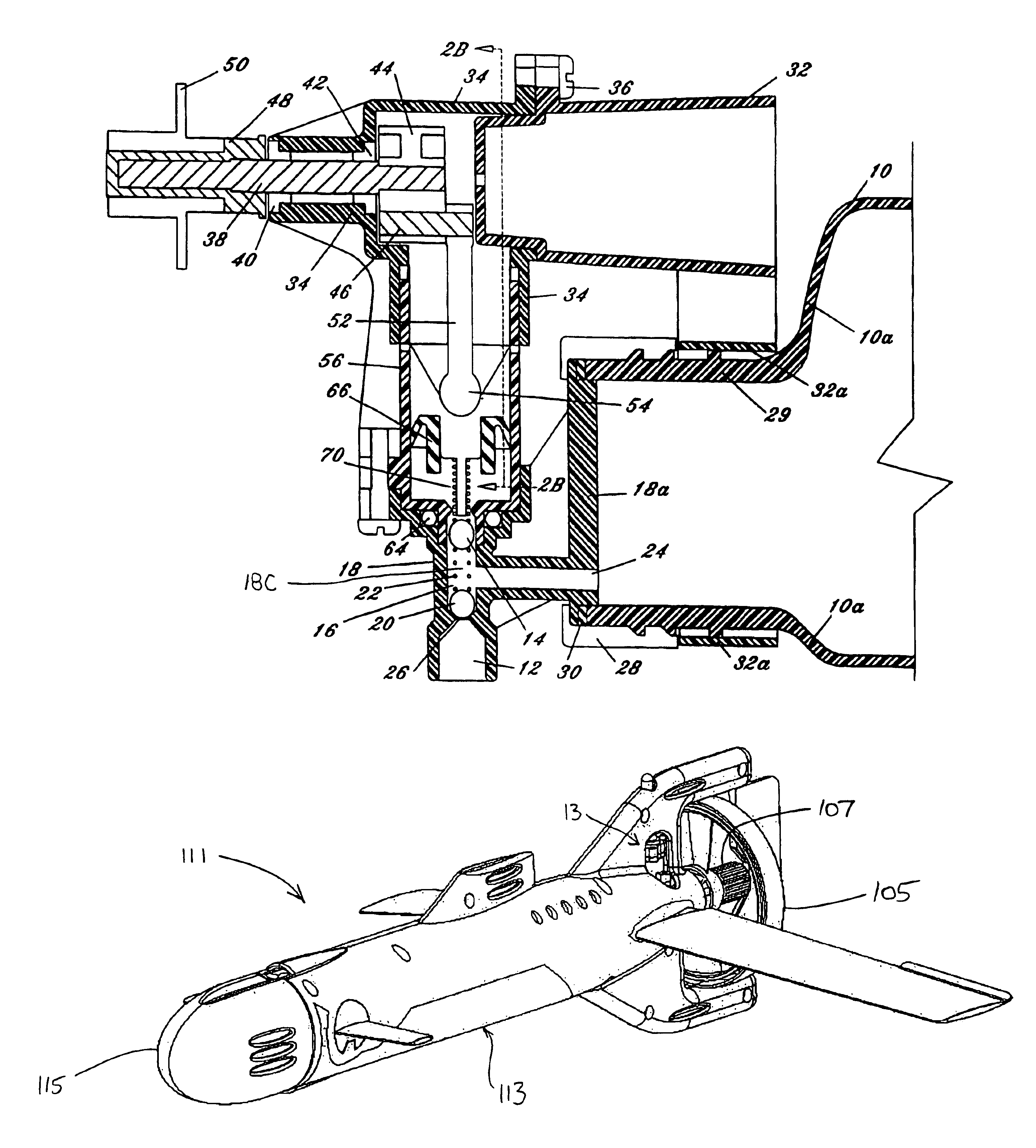
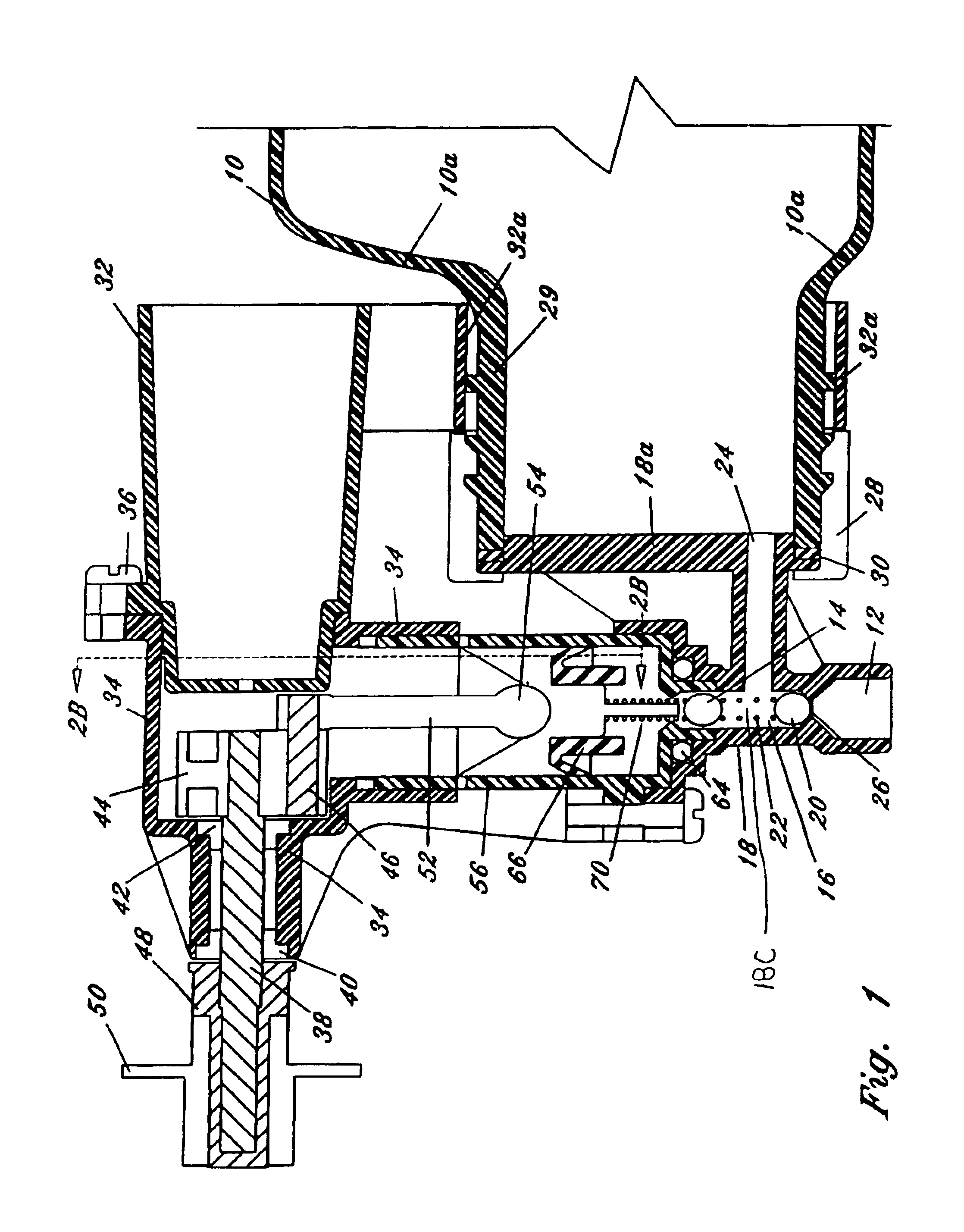
[0024]The present invention relates to a toy vehicle 11 having an engine 13 that is powered by a pump 9 and pressure vessel 10 that are both integral with the toy vehicle, as shown in FIGS. 10-13. Preferably, the engine is a pneumatic engine. The toy vehicle may be a submarine 111, as shown in FIGS. 12 and 13, or a plane (FIG. 9) or car, but is not limited to such embodiments.

[0025]A selectably pressurizable vessel 10 is shown in FIGS. 10 and 11. Preferably, pressure vessel 10 is made of a resilient polymeric plastic bottle. In one embodiment of the invention, the pressure vessel 10 has a capacity of about 2.5 liters with the range thereof preferably being between two and three liters. The pressure vessel 10 is integral with the toy vehicle. Preferably, the pressure vessel 10 is substantially disposed within the housing 113 of toy vehicle 11, as shown in FIGS. 12 and 13. Preferably, the housing (hull) 113 of the toy submarine 111 completely encloses the pressure vessel 10.

[0026]Pres...


PUM


Abstract

An integral pump assembly may be used to power a toy vehicle. The pump pressurizes fluid stored within the pressure vessel. The pressurized fluid within the pressure vessel drives the engine that powers the toy vehicle until the stored pressurized fluid has been depleted. The pump may then repressurize the pressure vessel to again drive the pneumatic engine. The pump is substantially disposed within the body of the toy vehicle.

Description

CROSS-REFERENCE TO RELATED APPLICATION[0001]This application claims the benefit under 35 U.S.C. § 119(e) of U.S. Provisional Application Ser. No. 60 / 344,054, filed Jan. 3, 2002, which is hereby incorporated by reference in its entirety.FIELD OF THE INVENTION[0002]The present invention relates to a toy vehicle. More particularly, the present invention relates to a toy vehicle having both an integral pump and vessel for powering an engine. Still more particularly, the present invention is for a toy submarine having an engine for powering the toy submarine, a vessel for storing fluid to drive the engine and a pump for supplying fluid to the vessel, each of which is integral with the toy submarine.BACKGROUND OF THE INVENTION[0003]Some existing toy vehicles having pneumatic engines have detachable pressure vessels for storing fluid. The pressure vessel is removed from a toy vehicle and pressurized by a separate pump. Once pressurized, the pressure vessel is reattached to the toy vehicle ...

Claims


Application Information

Patent Timeline
IPC IPC(8): A63H17/00A63H23/04A63H29/00A63H23/00A63H29/16A63H27/00F01B17/00F01B17/02A63H25/00
CPCA63H17/00A63H23/04A63H27/00A63H29/16F01B17/02A63H27/02
Inventor KOWNACKI, CHARLES D.
Owner SPIN MASTER LTD
Learn More