
Printing apparatus, printing apparatus control program, printing apparatus control method, printing data creating apparatus, printing data creating program and printing data creating method

a printing apparatus and control program technology, applied in the direction of digitally marking record carriers, instruments, image enhancement, etc., can solve the problems of difficult to provide a print head that never generates the ‘banding phenomenon, and the print quality is sometimes seriously degraded, so as to achieve the effect of more economical and convenient implementation of each modul

Inactive Publication Date: 2010-05-04
SEIKO EPSON CORP
View PDF23 Cites 13 Cited by
  • Summary
  • Abstract
  • Description
  • Claims
  • Application Information

AI Technical Summary

Benefits of technology

The invention provides a printing apparatus, method, and program that can improve the quality of printed images by reducing degradation caused by various factors such as banding, curved flight, and ink discharge deficiency. The invention achieves this by creating and manipulating image data in a way that minimizes the impact of these factors on the final printed image. The printing apparatus includes an image data acquiring module, N-ary image data creating module, image data area splitting module, pixel rearranging module, printing data creating module, and printing module. The N-ary image data is split into multiple image data areas that are likely to contain the same details of the image, and each pixel in each area is rearranged at a proper position in the image. This reduces the degradation of image quality caused by the banding phenomenon and other factors. The invention also provides a printing data creating program that includes information about the dot forming descriptions of the nozzle, which can be used to create high-quality printing results.

Problems solved by technology

Thus, as compared with a printing apparatus in other methods such as a laser printer using electrophotographic technology including a copier, it has a disadvantage that it takes longer to print.
Consequently, a print failure known as a so-called ‘banding (streaks) phenomenon’ is generated in the portion printed with the defective nozzle, and print quality is sometimes seriously degraded.
Therefore, in order to prevent a kind of printed failure like this ‘banding phenomenon’, studies and development are done in so-called hardware including improvements in fabrication techniques and in designs of the print head, but it is difficult to provide a print head that never generates the ‘banding phenomenon’ in view of fabrication cost and available hardware technology.
However, for portions with thick concentrations, in the schemes that information about the no discharge nozzle is distributed in right and left to prevent the ‘white streak phenomenon’ in the traditional techniques as Patent Reference 1 and Patent Reference 2, when it is adopted to ‘the curved flight phenomenon’ described above, it has a problem that banding still remains in portions with thick concentrations.
Moreover, in the scheme as traditional technique of the Patent Reference 3, no problem occurs when prints are solid images, but the scheme cannot be used for halftone prints.
Besides, the scheme that buries fine lines with other colors does not cause any problem for slight use, but for an image where different colors are created continuously, a problem remains that the hue of the image is partially changed similar to the former scheme.
Furthermore, in the scheme as the traditional technique of the Patent Reference 4, for the problem that dot forming descriptions are shifted, there is a problem that the process of proper feedback is complicated for difficult solution.
Moreover, in the scheme as the traditional technique of the Patent Reference 5, when dots have the γ property in creating dots in different size by surrounding nozzles after binarization, a problem occurs that the area ratio gray scale in that portion is likely to be deformed.
Furthermore, when there is only one type of forming size, information about dot size is unnecessary.
Furthermore, as described above, ‘the banding phenomenon’ is printed failure that ‘white streaks’ as well as ‘thick streaks’ are generated in the printed result at the same time caused by a so-called ‘curved flight phenomenon’ due to a nozzle whose dot forming position is shifted from an ideal forming position, printed failure that ‘white streaks’ and ‘thick streaks’ are generated in the printed result caused by ink discharge deficiency such as no ink discharge from a nozzle, and printed failure that ‘white streaks’ and ‘thick streaks’ are generated in the printed result caused by the γ properties of a dot.

Method used


Image

  • Printing apparatus, printing apparatus control program, printing apparatus control method, printing data creating apparatus, printing data creating program and printing data creating method
  • Printing apparatus, printing apparatus control program, printing apparatus control method, printing data creating apparatus, printing data creating program and printing data creating method
  • Printing apparatus, printing apparatus control program, printing apparatus control method, printing data creating apparatus, printing data creating program and printing data creating method

Examples


first embodiment

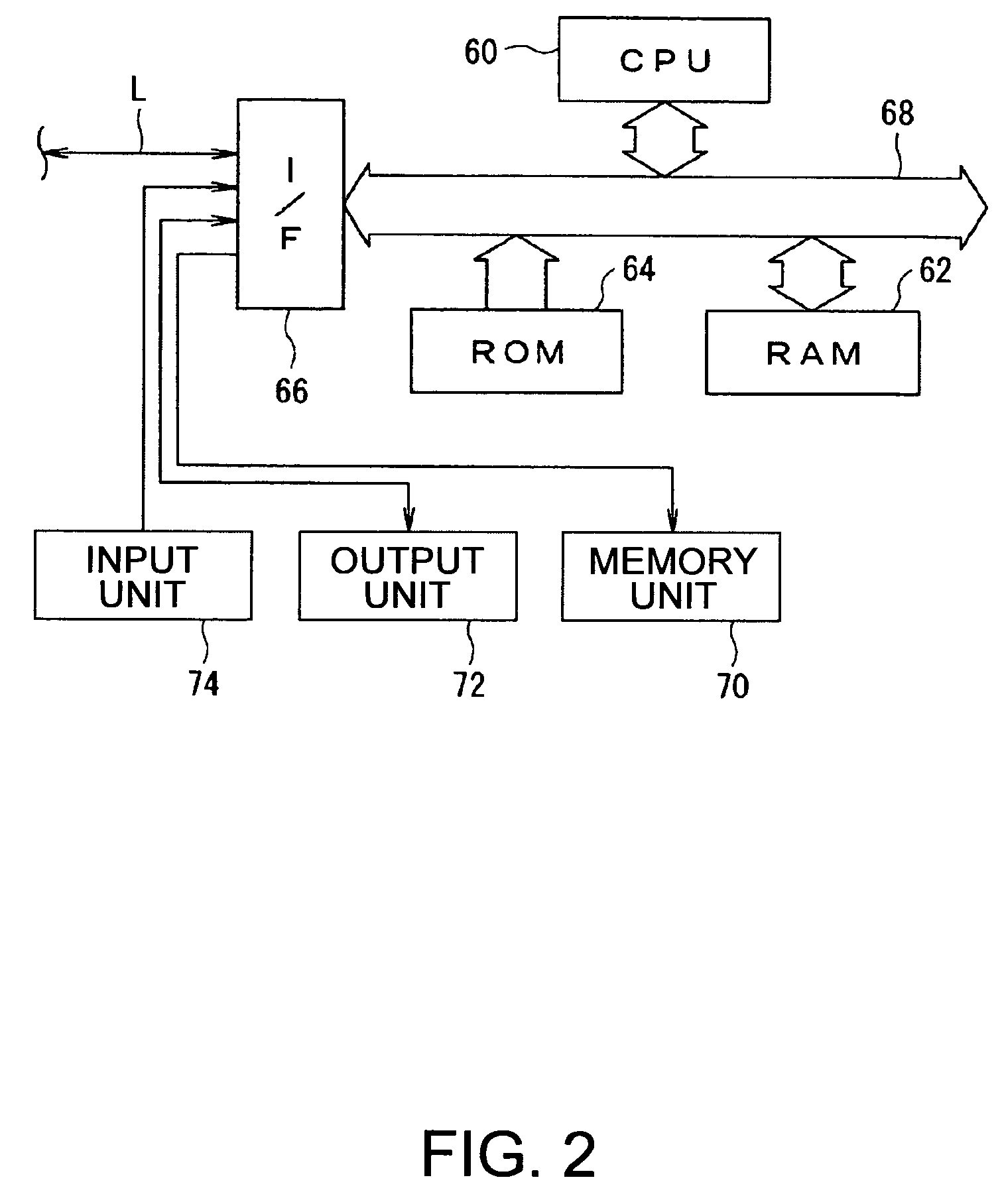
[0520]Hereinafter, a first embodiment according to the invention will be described wit reference to the drawings. FIGS. 1 to 13 are diagrams illustrating a first embodiment of a printing apparatus, a printing apparatus control program, a printing apparatus control method, a printing data creating apparatus, a printing data creating program, and a printing data creating method according to the invention.

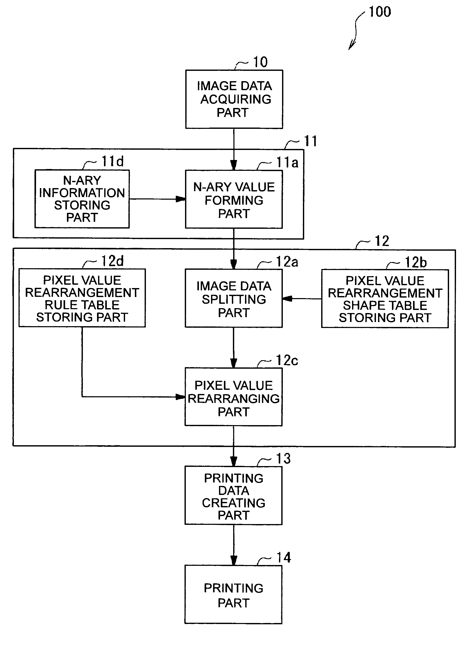
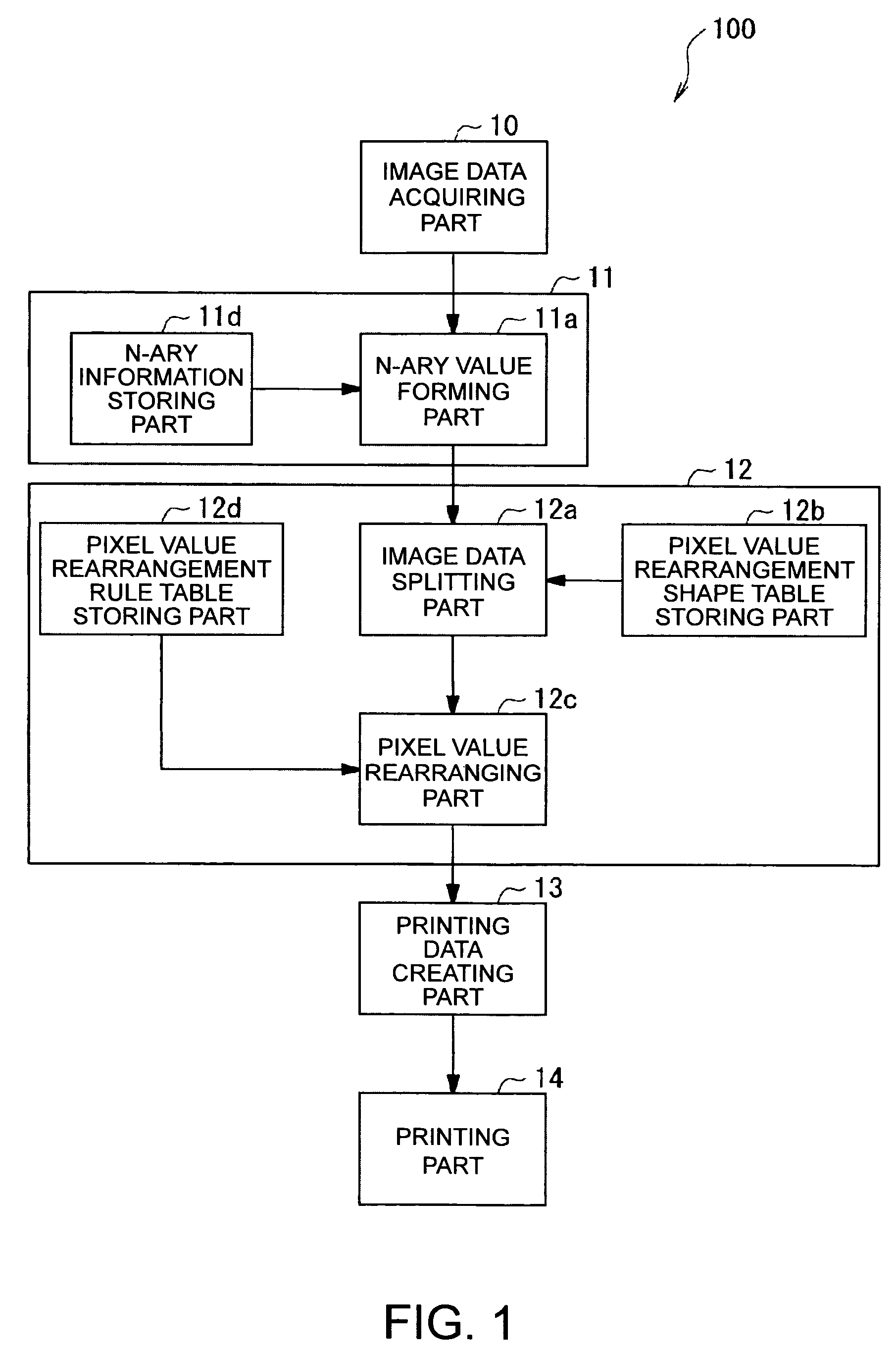
[0521]First, the configuration of a printing apparatus 100 according to the invention will be described with reference to FIG. 1. FIG. 1 is a block diagram illustrating the configuration of the printing apparatus 100 according to the invention.

[0522]The printing apparatus 100 is a line scan head type printing apparatus. As shown in FIG. 1, the apparatus is configured to include an image data acquiring part 10 which acquires M-ary image data (M≧3) from an external unit or a storage medium; an N-ary processing part 11 which conducts an N-ary formation process (M>N≧2) with respect to ima...

second embodiment

[0598]Next, a second embodiment according to the invention will be described with reference to the drawings. FIG. 14 to FIG. 21 are diagrams illustrating the second embodiment of the printing apparatus, the printing apparatus control program, the printing apparatus control method, the printing data creating apparatus, the printing data creating program, and the printing data creating method according to the invention.

[0599]The configuration of the printing apparatus of the embodiment is the configuration in which a nozzle property information storing part 12e which stores property information showing properties each of nozzles N in a print head 200 is added to the pixel value rearrangement processing part 12 of the printing apparatus 100 of the first embodiment shown in FIG. 1. The configuration of a computer system of the embodiment is the same as that of the first embodiment shown in FIG. 2. Furthermore, in the embodiment, the pixel value rearrangement process done at step S110 of...


PUM


Abstract

A printing apparatus for printing an image on a medium by a print head having a nozzle capable of creating dots includes: a module acquiring image data having an M-ary pixel data value (M≧3); a module creating N-ary image data (M>N≧2) from an M-ary pixel value (M≧3) expressed by each pixel data item; a module splitting the N-ary image data into a plurality of image data areas of a predetermined number of pixel data items; a module rearranging a position of a pixel corresponding to each pixel data item included in the image data areas in the N-ary image data at a predetermined position in each image data area; a module creating printing data defining dot forming information of each nozzle corresponding to the N-ary image data after rearrangement; and a module printing the image on the medium.

Description

RELATED APPLICATIONS[0001]This application claims priority to Japanese Patent Application Nos. 2005-027292 filed Feb. 3, 2005 and 2005-329135 filed Nov. 14, 2005 which are hereby expressly incorporated by reference herein in their entirety.BACKGROUND[0002]1. Technical Field[0003]The present invention relates to a printing apparatus, a printing apparatus control program, and a printing apparatus control method, which are used for printing equipment such as a facsimile machine, a copier, and Office Automation (OA) appliances, a printing apparatus, a printing apparatus control program, a printing apparatus control method, a printing data creating apparatus, a printing data creating program, and a printing data creating method particularly to so-called ink jet printing processing in which fine particles of multiple colors of liquid ink are discharged onto printing paper (recording material) to form predetermined letters and images.[0004]2. Related Art[0005]Hereinafter, a printing appara...

Claims


Application Information

Patent Timeline
Patent Type & Authority Patents(United States)
IPC IPC(8): H04N1/407G06K15/00H04N1/409G06T5/00
CPCH04N1/4015B41J2/2139
Inventor TAKAHASHI, TORU
Owner SEIKO EPSON CORP
Learn More