Optically based machine input control device

a control device and optical technology, applied in the direction of input/output for user-computer interaction, instruments, computing, etc., can solve the problems of small space occupation, sensitive control through small hand motions, and mechanical wear, and achieve the effect of simple construction

Inactive Publication Date: 2006-02-21
MCCAHON STEPHEN WILLIAM +1
View PDF11 Cites 15 Cited by
  • Summary
  • Abstract
  • Description
  • Claims
  • Application Information

AI Technical Summary

Benefits of technology

[0017]It is another object of the invention to prov...

Problems solved by technology

These apparatus, all capable of performing basic functions of an input device, each suffer from various deficiencies.
However, these devices are essentially two-dimensional control devices because they can only access two-dimensions simultaneously.
Furthermore, all the above-mentioned devices require physical contact between the operator and the control device, which causes mechanical wear.
When these devices are mounted on a keyboard or other primary input device, they are usually required to take up a small amount of space.
If the controlled parameters on the machine must cover a large scale compared to the required resolution, control through small hand motions is very sensitive and uncomfortable.
However, these devices are limited by the nature of the surface, the degrees of freedom of surface motion they can detect, and the need for mechanical interacti...

Method used


Image

  • Optically based machine input control device
  • Optically based machine input control device
  • Optically based machine input control device

Examples


Embodiment Construction

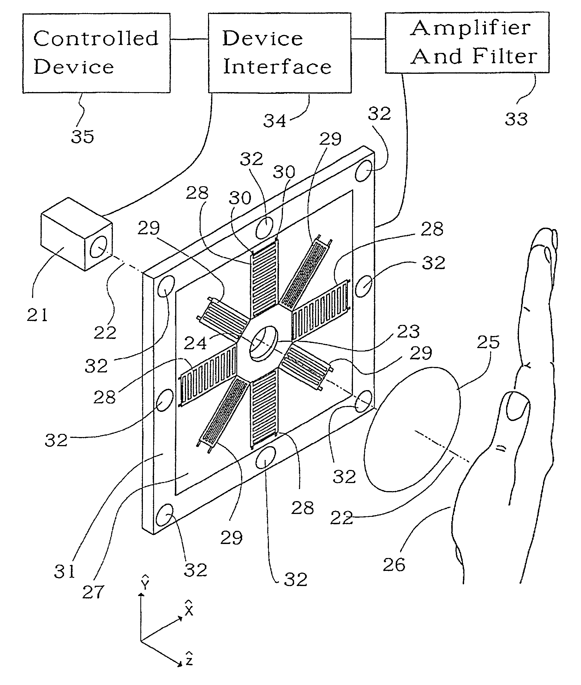
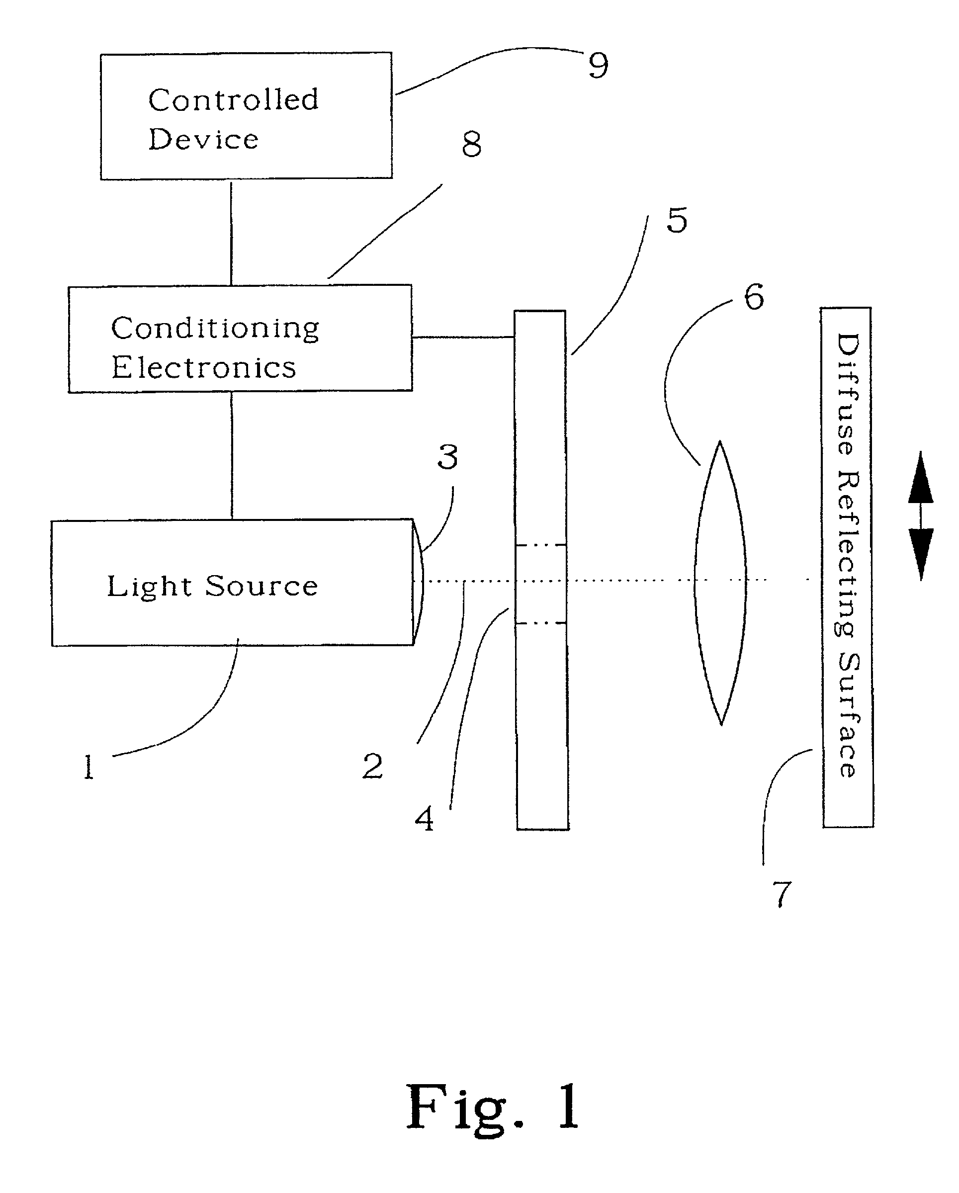
[0040]Referring to FIG. 1, an apparatus suitable for an optically based human-machine interface input control device comprises a light source 1, which produces optical radiation 2 which is transmitted through an aperture 4 in the center of a pattern analyzer 5, and a directing lens system 6, resulting in an illuminated region on a diffusely reflecting surface 7. A portion of the diffusely reflected light may be redirected back toward the pattern analyzer 5 by a collecting lens system 6 to form a pattern at the surface of the pattern analyzer 5. The diffusely reflecting surface 7 may be translated along or rotated about one or more of the three orthogonal axes, causing the irradiance distribution of the pattern illuminating the surfaces of the pattern analyzer array 5 to be modified in a related manner. The pattern analyzer 5 generates electrical signals representing localized measurements of the direction, rate of motion, and irradiance distribution of an optical pattern. Electrical...


PUM


Abstract

A non-contact optically based apparatus for measuring the motion of a diffusely reflecting surface. The motion measurements and signals derived therefrom are used to provide input control signals to a computer or other electronic control systems requiring a human tactile or other control. The apparatus includes a unique optical sensor which senses both the magnitude and direction of the motion of a surface, relative to the apparatus, by measuring the motion of the pattern generated by illuminating the diffusely reflecting surface with a light source.

Description

TECHNICAL FIELD[0001]This invention relates generally to optical tracking and human-machine input devices. More particularly this patent discloses a non-contact, optically- based tracking device for use as an input control device in a computer system or other electronic control system requiring a human-machine tactile interface or other control.BACKGROUND OF THE INVENTION[0002]Currently, most apparatus used as human tactile input devices to control electronic systems, such as computers, use mechanical, electronic, optical, or some combination of these means to measure a force, velocity, or displacement that is converted to a parameter suitable for input to the system. The most common are mechanical or optically based and they typically control a cursor motion, an object selection, scrolling, or other operator input commands based upon visual feedback from a display device while the system under control is executing a function. Mouse devices, track-ball devices, joystick devices, and...

Claims


Application Information

Patent Timeline
IPC IPC(8): G09G5/00G06F3/03G06F3/033G06F3/042
CPCG06F3/0317G06F3/0421G06F3/03549
Inventor MCCAHON, STEPHEN WILLIAMLUNDQUIST, PAUL B.
Owner MCCAHON STEPHEN WILLIAM
Why Eureka
Try Eureka