Imaging device, imaging method, and image processing device

a technology of image processing and imaging method, which is applied in the field of imaging device, imaging method, and image processing device, can solve the problems of image quality degradation of original image data, and achieve the effect of effectively preventing image quality

Active Publication Date: 2016-04-28
FUJIFILM CORP
View PDF6 Cites 14 Cited by
  • Summary
  • Abstract
  • Description
  • Claims
  • Application Information

AI Technical Summary

Benefits of technology

[0009]The above-mentioned restoration processing is processing of restoring a blurred image, which is blurred due to a point spread phenomenon (imaging optical characteristics) of an optical system as one of optical characteristics, to an original sharp image. The processing is a technique of acquiring a recovery image, in which degradation in image quality is eliminated, by applying a restoration filter based on the point spread function to data of an original image of which an image quality is degraded.
[0010]Hence, degradation in image quality caused by the point spread phenomenon of the optical system is accurately detected, and the restoration filter capable of accurately eliminating the degradation in image quality is designed. When the degradation in image quality caused by the point spread phenomenon of the optical system is accurately reflected in the original image data, in principle, it is possible to obtain “a high-quality image in which a subject image is reproduced with high fidelity” from “a photographed image of which an image quality is degraded”.

Problems solved by technology

However, in accordance with a subject image or characteristics of photographing apparatuses, “the property of the restoration filter” may be inappropriate for “the degradation in image quality of the original image data”.

Method used


Image

  • Imaging device, imaging method, and image processing device
  • Imaging device, imaging method, and image processing device
  • Imaging device, imaging method, and image processing device

Examples


first embodiment

[0102]The present embodiment will describe an example where image quality is prevented from being degraded by overcorrection and the like, which are caused by the restoration processing performed on the defocused image, by controlling the restoration processing on the basis of “the amount of movement of the subject” in the optical axis direction of the optical system 12.

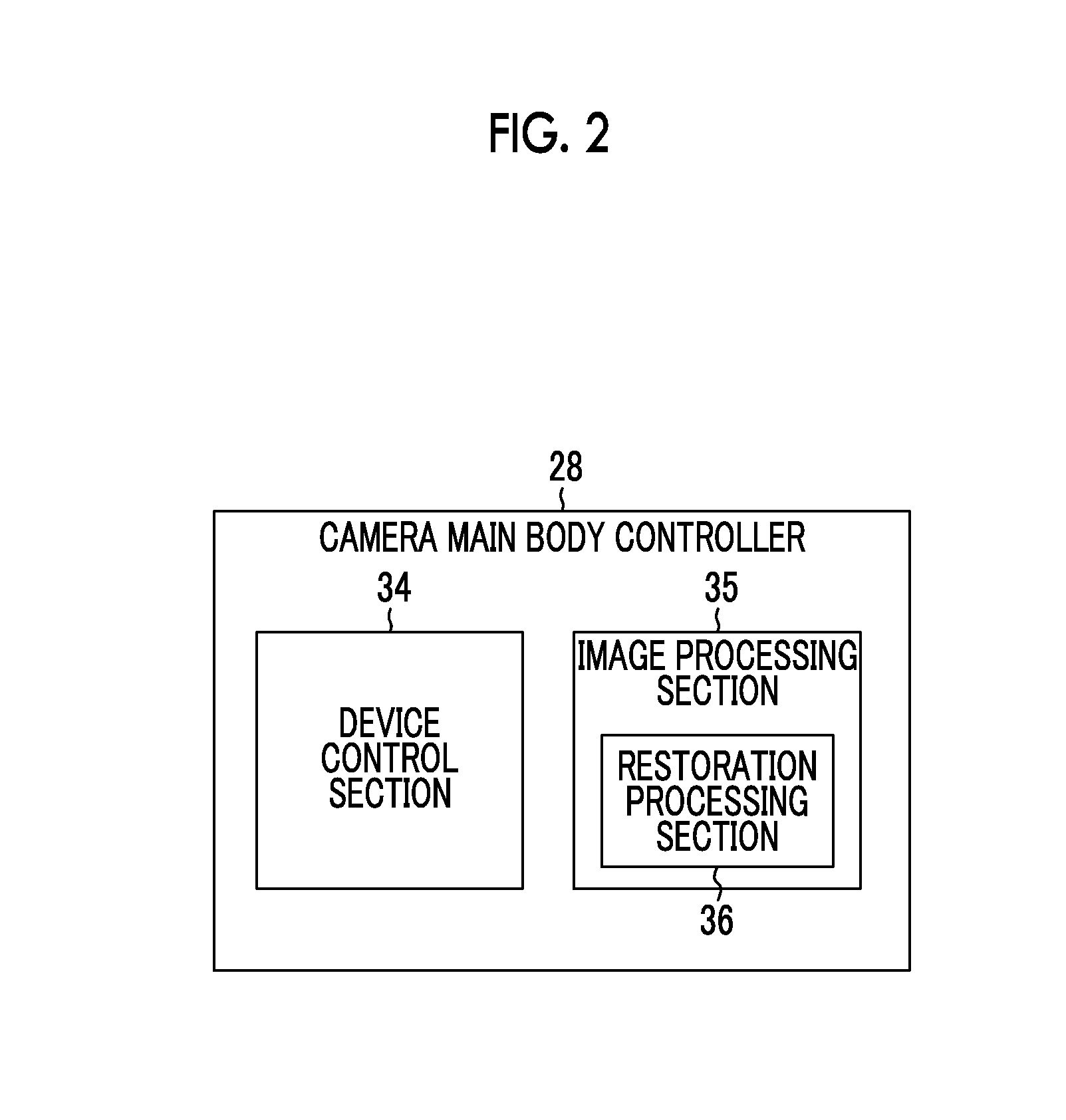
[0103]FIG. 5 is a functional block diagram illustrating the restoration processing of a first embodiment, and shows various functional blocks constituting the image processing section 35 (refer to FIG. 2). It should be noted that the functional blocks in the drawing are not necessarily separately provided and the plurality of functional blocks may be implemented by hardware and / or software incorporated therein.

[0104]The image processing section 35 includes an image adjustment section 100, a subject distance acquisition section 115, a movement amount acquisition section 120, a restoration processing determination sect...

second embodiment

[0140]The present embodiment will describe an example where image quality is prevented from being degraded by overcorrection and the like, which are caused by the restoration processing performed on the defocused image, by controlling autofocusing (tracking autofocusing) on the basis of “the amount of movement of the subject” in the optical axis direction of the optical system 12.

[0141]In the present embodiment, configurations and effects the same as those of the above-mentioned first embodiment will be omitted.

[0142]FIG. 12 is a functional block diagram illustrating the restoration processing of a second embodiment, and shows various functional blocks constituting the image processing section 35 (refer to FIG. 2). The image processing section 35 of the present embodiment has not only the functional blocks (refer to FIG. 5) according to the above-mentioned first embodiment but also an auto focus section 140 and a tracking auto focus determination section 145.

[0143]The auto focus sec...

third embodiment

[0158]In the present embodiment, a description will be given of an example in which the restoration processing is controlled on the basis of “the frame rate” so as to prevent image quality from being graded by the restoration processing.

[0159]In the present embodiment, configurations and effects the same as those of the above-mentioned first embodiment will be omitted.

[0160]FIG. 15 is a functional block diagram illustrating the restoration processing of a third embodiment, and shows various functional blocks constituting the image processing section 35 (refer to FIG. 2). The image processing section 35 of the present embodiment has not only the functional blocks (refer to FIG. 5) according to the above-mentioned first embodiment but also a frame rate setting section 150.

[0161]The frame rate setting section 150 sets a frame rate for generation of the successive images such as a moving image in the imaging section 11, and controls generation of the plurality of successive images perfo...


PUM


Abstract

An imaging device 10 according to one aspect of the present invention includes: a subject distance acquisition section 115; a movement amount acquisition section 120 that acquires an amount of movement of the subject on the basis of the subject distance; a restoration processing determination section 125 that determines, on the basis of the amount of movement acquired by the movement amount acquisition section 120, whether the restoration processing should be performed on the images through a restoration filter, a restoration strength of the restoration processing should be adjusted and the restoration processing should be performed on the images, or the restoration processing should not be performed on the images; and a restoration processing execution section 105 that performs the restoration processing on the images through the restoration filter or with the adjusted restoration strength, on the basis of the determination of the restoration processing determination section 125.

Description

CROSS-REFERENCE TO RELATED APPLICATIONS[0001]This application is a Continuation of PCT International Application No. PCT / JP2014 / 067106 filed on Jun. 27, 2014, which claims priority under 35 U.S.C §119(a) to Patent Application No. 2013-160768 filed in Japan on Aug. 1, 2013, all of which are hereby expressly incorporated by reference into the present application.BACKGROUND OF THE INVENTION[0002]1. Field of the Invention[0003]The present invention relates to an imaging device, an imaging method, and an image processing device. In particular, the present invention relates to an imaging device, an imaging method, and an image processing device capable of performing restoration processing based on a point spread function.[0004]2. Description of the Related Art[0005]On an image of a subject photographed through an optical system, sometimes, a so-called point spread phenomenon may be observed. The point spread phenomenon is a phenomenon that a point subject is slightly enlarged by an effect...

Claims


Application Information

Patent Timeline
Patent Type & Authority Applications(United States)
IPC IPC(8): H04N5/357G06T5/10G06T5/00
CPCH04N5/357G06T5/10G06T5/001G06T5/003G06T2207/10016G06T5/20G06T2207/20201H04N23/672H04N23/673H04N23/635H04N23/80H04N25/6153H04N25/60
Inventor HAYASHI, KENKICHISUGIMOTO, MASAHIKONARUSE, YOUSUKEIRIE, KOSUKE
Owner FUJIFILM CORP
Why Eureka
Try Eureka