Planar antenna structure

a technology of antenna structure and antenna, applied in the direction of simultaneous aerial operation, antenna details, antennas, etc., can solve the problems of insufficient bandwidth for modern communications devices, may have short circuit points, and the requirements of antennas have become more severe, and achieve wideband antennas, reliable dual resonance, and simple structure

Inactive Publication Date: 2005-07-26
CANTOR FITZGERALD SECURITIES
View PDF20 Cites 46 Cited by
  • Summary
  • Abstract
  • Description
  • Claims
  • Application Information

AI Technical Summary

Benefits of technology

[0008]An advantage of the invention is that with a relatively simple structure a reliable dual resonance can be achieved and, hence, a relatively wideband antenna when the resonances are close to each other. Another advantage of the invention is that a relatively large gain can be achieved for the antenna by utilizing overlapping resonances. A further advantage of the invention is that the antenna can be easily made a dual-band antenna by arranging the resonance frequencies such that they fall into the

Problems solved by technology

In portable radio apparatuses, especially in mobile stations, the antenna requirements have become more severe.
It, too, may have a short-circuit point.
One drawback of the above-described antennas according to the prior art is that their bandwidth is not always large enough for modern communications devices.
Radiating elements may be designed such that the bandwidth is increased through two adjacent resonance frequencies, but then the disadvantage of the structure is that the structure is

Method used


Image

  • Planar antenna structure
  • Planar antenna structure
  • Planar antenna structure

Examples


Embodiment Construction

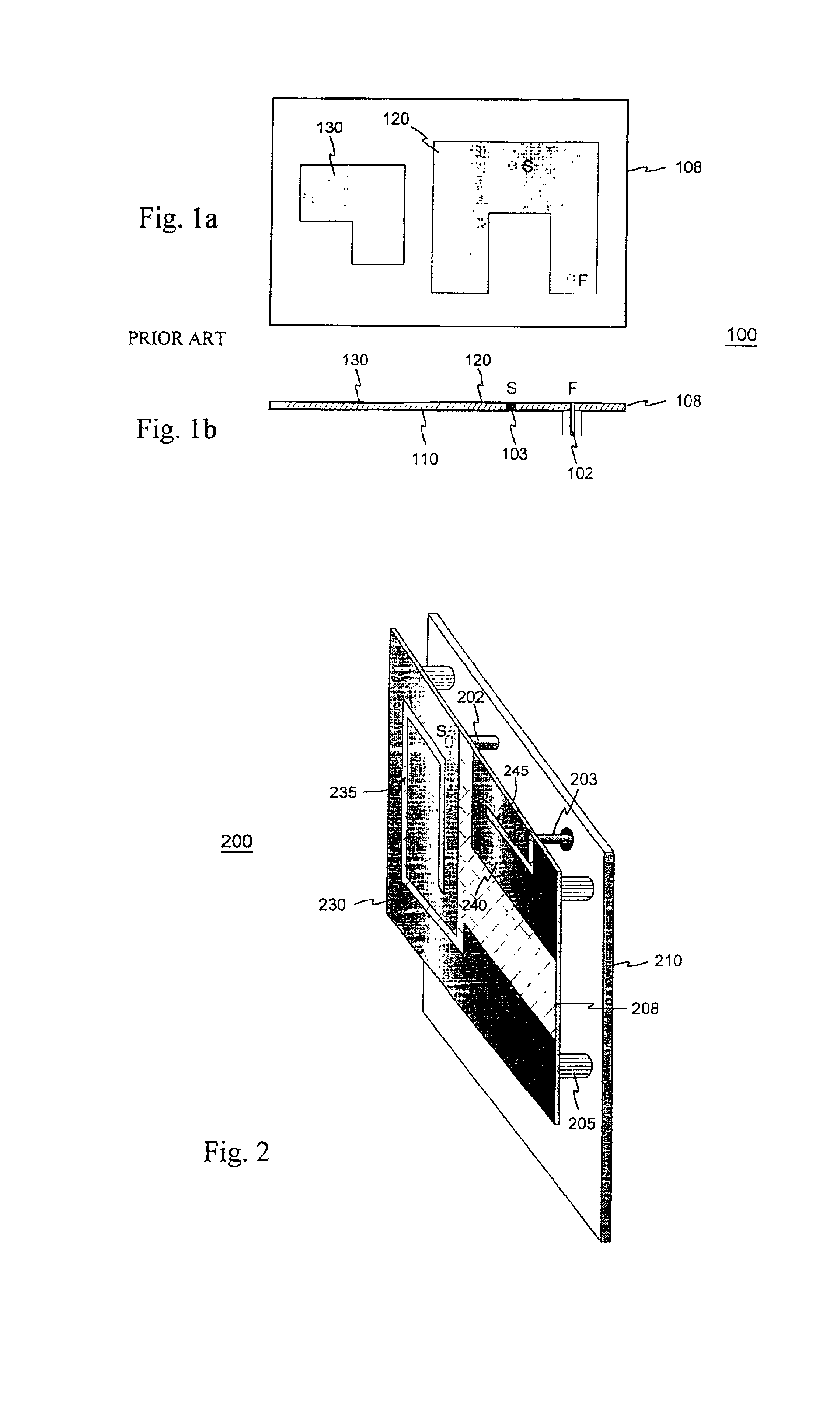
[0017]FIG. 1 was already discussed in conjunction with the description of the prior art.

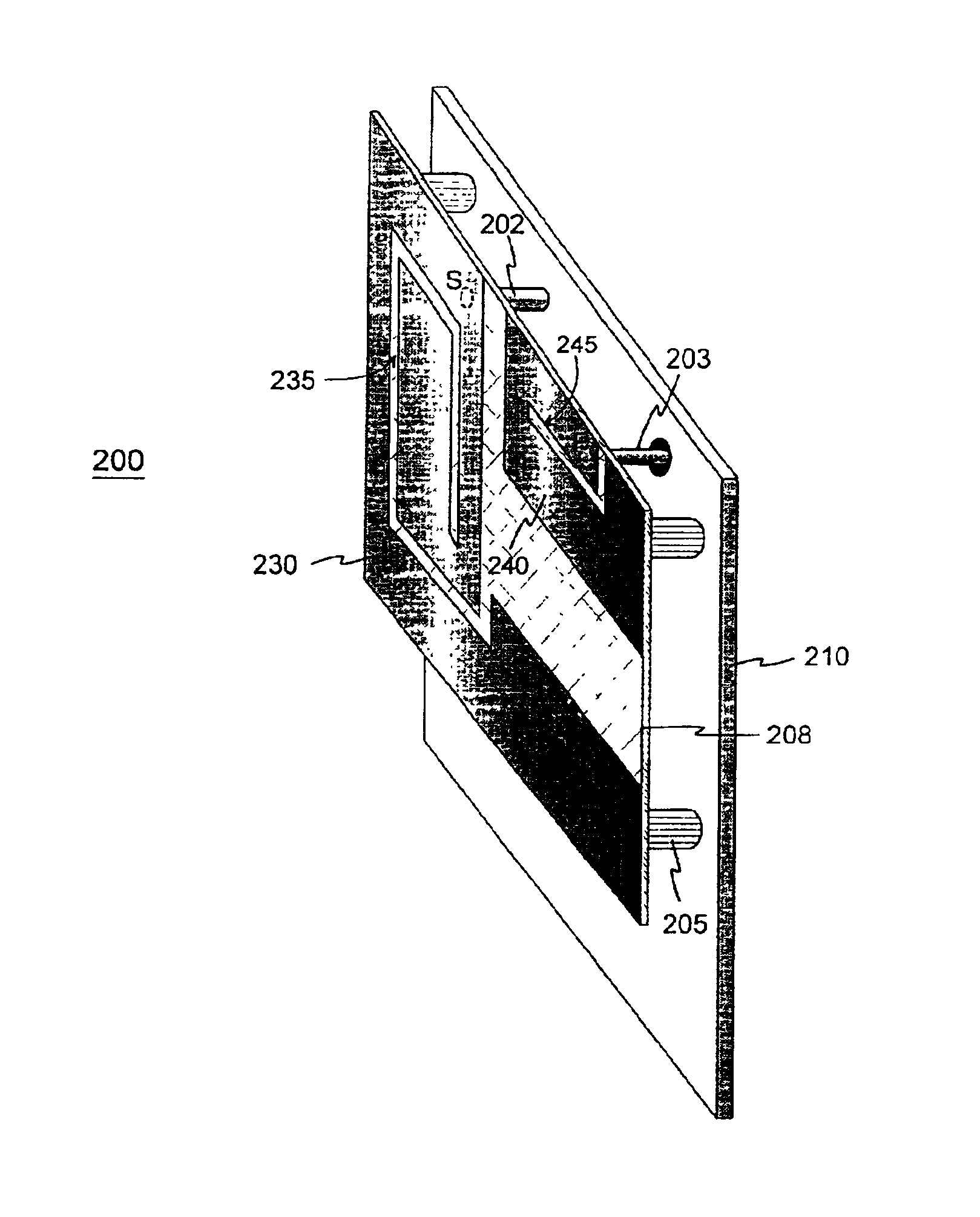
[0018]FIG. 2 shows an example of an antenna structure according to the invention. In this example the antenna 200 comprises a ground plane 210 and a parallely positioned dielectric plate 208, attached to the ground plane through insulating pieces such as 205. On the outer surface, as viewed from the ground plane, of the dielectric plate 208 there are two separate planar conductive regions: a parasitic element 230 and feed element 240. On the ground-plane-side surface of the dielectric plate 208 there are no conductive regions. The parasitic element is short-circuited at a point S to the ground plane through conductor 202. The radiating parasitic element 230, short-circuit conductor 202 and ground plane thus constitute the PIFA-part of the antenna. The feed conductor 203 of the whole antenna structure is in galvanic contact with the feed element 240 at a point F. The feed element has two functions...


PUM


Abstract

The invention relates to planar antennas the structural components of which include a parasitic element. The antenna structure comprises a PIFA-type structure (230, 210, 202) to be placed inside the covers of a mobile station. The PIFA is fed parasitically e.g. through a conductive strip (240) placed on the same insulating board. The feed conductor (203) of the whole antenna structure is in galvanic contact with this feed element; a short-circuit point the feed element doesn't have. The feed element (240) also serves as an auxiliary radiator. The resonance frequencies of the antenna elements or their parts are arranged according to need so as to overlap, to be close to each other or to be relatively wide apart. The structure may also comprise a whip element in connection with the feed element. According to the invention, a relatively simple structure provides a reliable dual resonance and, hence, a relatively wideband antenna when the resonances are close to each other. Moreover, no polarization rotation takes place in the antenna radiation inside the frequency band realized through the dual resonance.

Description

FIELD OF INVENTION[0001]The invention relates to planar antennas the structural parts of which include a parasitic element. The antenna finds particular utility in mobile stations which require a relatively wide band or which are to be used in two or more frequency bands.BACKGROUND[0002]In portable radio apparatuses, especially in mobile stations, the antenna requirements have become more severe. As the devices continue to shrink in size, the antenna naturally has to be small; preferably it is placed inside the covers of the apparatus. On the other hand, together with the introduction of new frequencies there has been a growing demand for mobile stations in which the antenna must function in two or more frequency bands. In addition, in dual-band antennas the upper operating band at least should be relatively wide, especially if the device in question is to be used in more than one system utilizing the 1.7 to 2-GHz range.[0003]Antenna requirements may be met through various structura...

Claims


Application Information

Patent Timeline
IPC IPC(8): H01Q9/04H01Q5/00H01Q1/24H01Q5/392
CPCH01Q1/243H01Q5/392H01Q9/0421
Inventor ANNAMAA, PETTERIMIKKOLA, JYRKI
Owner CANTOR FITZGERALD SECURITIES
Why Eureka
Try Eureka