
Antenna with heat dissipation function for gateway equipment

A gateway device and antenna technology, which is applied to antennas, loop antennas, antenna parts, etc., can solve the problems of time-consuming and labor-intensive replacement of high-gain antennas, inability to effectively dissipate heat, and inability to replace them, so as to achieve a simple overall structure and heat dissipation effect Good, the effect of increasing the current amplitude

Active Publication Date: 2019-12-17
武汉慧联无限科技有限公司
View PDF16 Cites 0 Cited by
  • Summary
  • Abstract
  • Description
  • Claims
  • Application Information

AI Technical Summary

Problems solved by technology

[0002] Gateway equipment is a device connected to various LANs and WANs in the Internet. It is used almost everywhere connected to the Internet. However, most of the existing methods for enhancing the received signal are to replace higher-gain antennas. However, the antennas of some gateway equipment and the gateway equipment It is directly connected together and cannot be replaced, and it is time-consuming and laborious to replace the high-gain antenna. In order to increase the strength of the existing antenna, multiple groups of branches are set on the wire. The increase of the branches will increase the power, which will make the antenna heat and cannot be used. effective heat dissipation

Method used


Image

  • Antenna with heat dissipation function for gateway equipment
  • Antenna with heat dissipation function for gateway equipment
  • Antenna with heat dissipation function for gateway equipment

Examples


Embodiment Construction

[0023] The following will clearly and completely describe the technical solutions in the embodiments of the present invention with reference to the accompanying drawings in the embodiments of the present invention. Obviously, the described embodiments are only some, not all, embodiments of the present invention. Based on the embodiments of the present invention, all other embodiments obtained by persons of ordinary skill in the art without making creative efforts belong to the protection scope of the present invention.

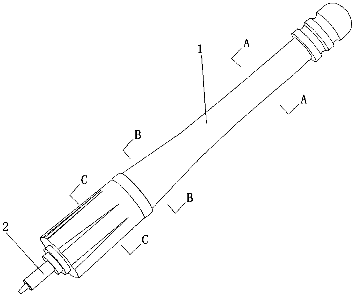
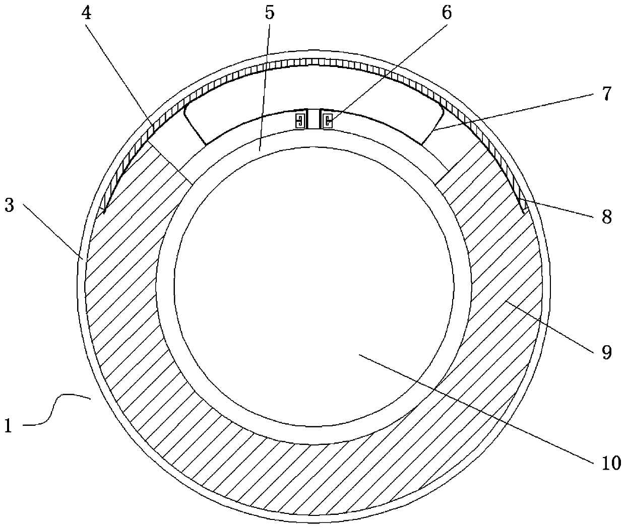
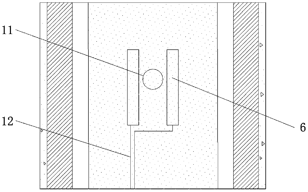
[0024] see Figure 1-6 , the present invention provides a technical solution: an antenna with a heat dissipation function for gateway equipment, including an antenna body 1 and an antenna connector 2, the antenna connector 2 is installed at the lower end of the antenna body 1, and the outer side of the antenna body 1 is sprayed with a heat dissipation Layer 3, the antenna body 1 is a carbon nano heat dissipation coating, and the dielectric substrate 9 inside t...


PUM


Abstract

The invention discloses an antenna with a heat dissipation function for gateway equipment. The antenna comprises an antenna body and an antenna connector. The lower end of the antenna body is providedwith an antenna connector. A floor is arranged in a heat dissipation layer; a dielectric substrate is arranged between the heat dissipation layer and the floor; an empty groove for installing resonance metal sheets is formed between the heat dissipation layer at the front end of the dielectric substrate and the floor; a feeder line is connected under a resonance assembly; branches are connected in the side surfaces of the resonance metal sheets, and the branches are arranged on the dielectric substrate; and the outer side of the dielectric substrate and the outer side of the resonance metal sheet are connected to the heat dissipation layer through heat dissipation glue. According to the antenna with the heat dissipation function for the gateway equipment, the dielectric substrate is of avariable-diameter cylindrical structure, and the floor and the resonance metal sheets are conformal with the dielectric substrate; the performance requirements for wide wave and high gain and the likeare met through different sizes of resonance metal sheets; and the branches and the resonance metal sheets are provided with the heat dissipation glue, and the branches are connected with the outermost heat dissipation layer, so that the heat dissipation effect is better.

Description

technical field [0001] The invention relates to the field of antennas for gateway equipment, in particular to an antenna with heat dissipation function for gateway equipment. Background technique [0002] Gateway equipment is a device connected to various LANs and WANs in the Internet. It is used almost everywhere connected to the Internet. However, most of the existing methods for enhancing the received signal are to replace higher-gain antennas. However, the antennas of some gateway equipment and the gateway equipment It is directly connected together and cannot be replaced, and it is time-consuming and laborious to replace the high-gain antenna. In order to increase the strength of the existing antenna, multiple groups of branches are set on the wire. The increase of the branches will increase the power, which will make the antenna heat and cannot be used. Effectively dissipate heat. Contents of the invention [0003] The purpose of the present invention is to provide ...

Claims


Application Information

Patent Timeline
IPC IPC(8): H01Q1/00H01Q1/38H01Q1/48H01Q1/50H01Q5/10H01Q5/28H01Q5/50H01Q7/00H01Q1/22
CPCH01Q1/02H01Q1/2291H01Q1/38H01Q1/48H01Q1/50H01Q7/00H01Q5/10H01Q5/28H01Q5/50
Inventor 杨广学
Owner 武汉慧联无限科技有限公司
Learn More