CDMA demodulation circuit and CDMA demodulation method

Inactive Publication Date: 2005-07-26
LENOVO INNOVATIONS LTD HONG KONG
View PDF19 Cites 23 Cited by
  • Summary
  • Abstract
  • Description
  • Claims
  • Application Information

AI Technical Summary

Benefits of technology

[0007]Therefore, the object of the invention consists in providing a CDMA demodulation circuit and method which are capable of maintaining good reception quality even in a mobile environment by estimating a time at which the level drops due to fading and by controlling assignment of path timing to a fingers portion before the level actually drops.
[0008]For solution of the above mentioned problem, the present invention is the CDMA demodulation circuit comprising delay profile calculating means for calculating delay profiles of received signals; path assigning means for assigning path locations to a plurality of fingers based on the calculation result obtained in the delay profile calculating means; the plurality of fingers to which the path locations are assigned by the path assigning means, the fingers de-spreading the assigned paths; and rake combining means for combining output of the plurality of fingers. This demodulation circuit is characterized by comprising reception controlling means that estimates a drop cycle of the reception level from the reception level combined by the rake combining means and that reduces degradation in receiving characteristics using the estimation result.
[0009]Further, another invention according to the present invention is the demodulation method for the CDMA demodulation circuit comprising the delay profile calculating means for calculating delay profiles of received signals; the path assigning means for assigning path locations to the plurality of fingers based on the calculation result obtained in the delay profile calculation means; the plurality of fingers to which the path locations are assigned by the path assigning means, the fingers de-spreading the assigned paths; and the rake combining means for combining output of the plurality of fingers. This demodulation method is characterized by comprising a first step of estimating the drop cycle of the reception level from the reception level combined by the rake combining means to reduce degradation in receiving characteristics using the estimation result.
[0010]The present invention and the other invention according to the present invention make it possible to maintain good reception quality even in a mobile environment by estimating the time at which the level drops due to fading, and by controlling the assignment of path timing to the fingers portion before the level actually drops.

Problems solved by technology

Conventionally, there has been a drawback in the mobile communication environment that fading occurs by transmitted radio waves being reflected and diffracted so that accurate timing of paths cannot be estimated, which causes degradation in receiving characteristics.

Method used


Image

  • CDMA demodulation circuit and CDMA demodulation method
  • CDMA demodulation circuit and CDMA demodulation method
  • CDMA demodulation circuit and CDMA demodulation method

Examples


Embodiment Construction

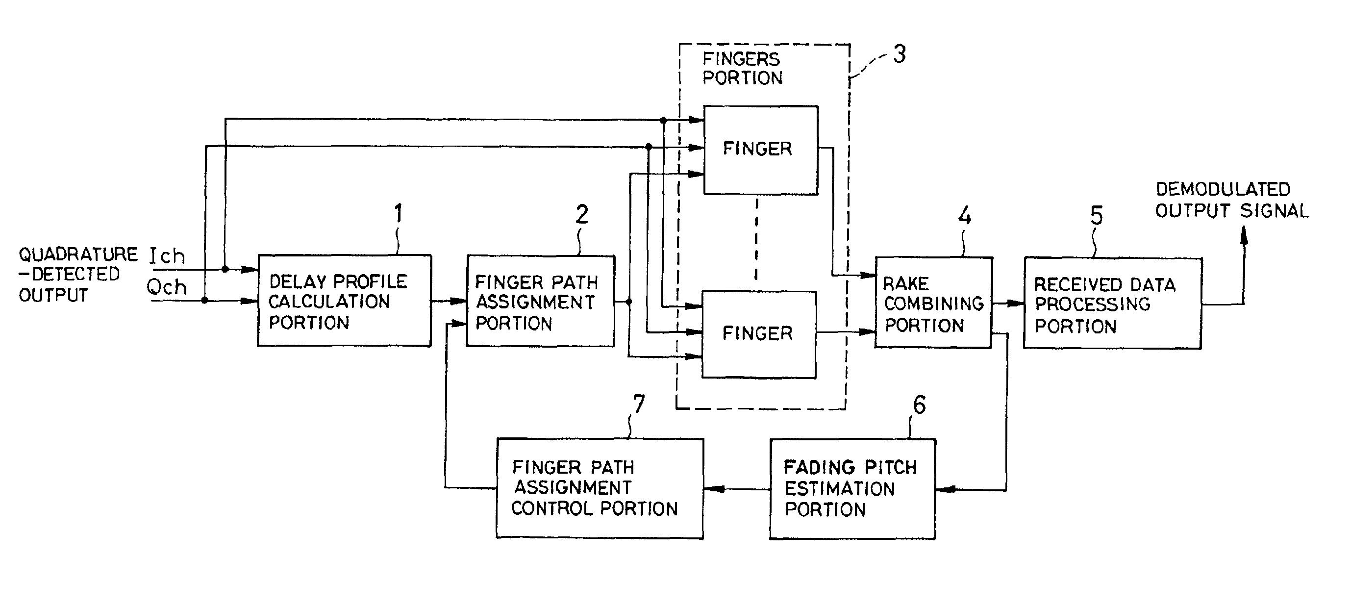
[0021]Firstly, an outline of the present invention will be described. Referring to a block diagram of a CDMA demodulation circuit in FIG. 1, a fingers portion 3 performs de-spreading, and a rake combining portion 4 determines a reception level. A fading pitch estimation portion 6 estimates a drop cycle of the reception level from the obtained reception level, and a finger path assignment control portion 7 uses the result to control a finger path assignment portion 2. In this manner, good receiving characteristics can be achieved even in a mobile communication environment by monitoring the reception level and avoiding use of data in a poor receiving condition to update path locations for assigning to the fingers.

[0022]The embodiments of the present invention will be described below with reference to the appended drawings. FIG. 1 is a block diagram of a first embodiment of the CDMA demodulation circuit according to the present invention. Referring to FIG. 1, the CDMA demodulation circ...


PUM


Abstract

To provide a CDMA demodulation circuit and a CDMA demodulation method capable of maintaining good receiving characteristics even in a mobile communication environment. A fading pitch estimation portion estimates a time at which a level of a received input signal drops due to fading by monitoring fluctuation in the level provided by a rake combining portion. Before the level drops, a finger path assignment control portion controls assignment of path timing to a fingers portion performed by a finger path assignment portion.

Description

BACKGROUND OF THE INVENTION[0001]1. Field of the Invention[0002]The present invention relates to a Code Division Multiple Access (CDMA) demodulation circuit and a CDMA demodulation method, and more particularly to the CDMA demodulation circuit and the CDMA demodulation method used for mobile communication devices.[0003]2. Description of the Related Art[0004]Conventionally, there has been a drawback in the mobile communication environment that fading occurs by transmitted radio waves being reflected and diffracted so that accurate timing of paths cannot be estimated, which causes degradation in receiving characteristics. Hence, examples of means for solving this drawback have been disclosed in a Japanese Patent Laid-Open No. 11-4213 (hereafter referred to as a document 1), a Japanese Patent Laid-Open No. 11-274982 (hereafter referred to as a document 2), a Japanese Patent Laid-Open No. 10-271034 (hereafter referred to as a document 3), a Japanese Patent Laid-Open No. 11-251962 (herea...

Claims


Application Information

Patent Timeline
IPC IPC(8): H04B1/707H04B1/7113H04B1/7117H04B7/26H04L7/00H04W88/02
CPCH04B1/7113H04B1/7117
Inventor TAMURA, KOICHI
Owner LENOVO INNOVATIONS LTD HONG KONG
Why Eureka
Try Eureka