
Device and method for a transmitter/receiver device of a bus system

Active Publication Date: 2021-03-18
ROBERT BOSCH GMBH
View PDF0 Cites 1 Cited by
  • Summary
  • Abstract
  • Description
  • Claims
  • Application Information

AI Technical Summary

Benefits of technology

The patent describes a device and method that can optimize the reception of messages in a bus system by ensuring good quality and high data rates. This is achieved by measuring the minimum time needed for a message to transition between different voltage states on the bus and calculating a power-on period to reduce oscillations and tendency. The device allows for flexibility in bus topology and the number of nodes, while ensuring ideal performance during transition of the bus signal. The technical effects are improved data transmission and reduced oscillation tendency in the bus system.

Problems solved by technology

This is a great disadvantage in the system configuration because the bit time must therefore last until the oscillation is sufficiently damped.
If the bit time is too short and the recessive state is therefore not stable, the transmitter / receiver device may erroneously detect a dominant state.
This causes an undesired reduction of the bit rate.
However, depending on the actually prevailing system conditions, it is problematic that the length of a recessive bit may shrink to a fraction of the nominal bit length nevertheless.

Method used


Image

  • Device and method for a transmitter/receiver device of a bus system
  • Device and method for a transmitter/receiver device of a bus system
  • Device and method for a transmitter/receiver device of a bus system

Examples


Embodiment Construction

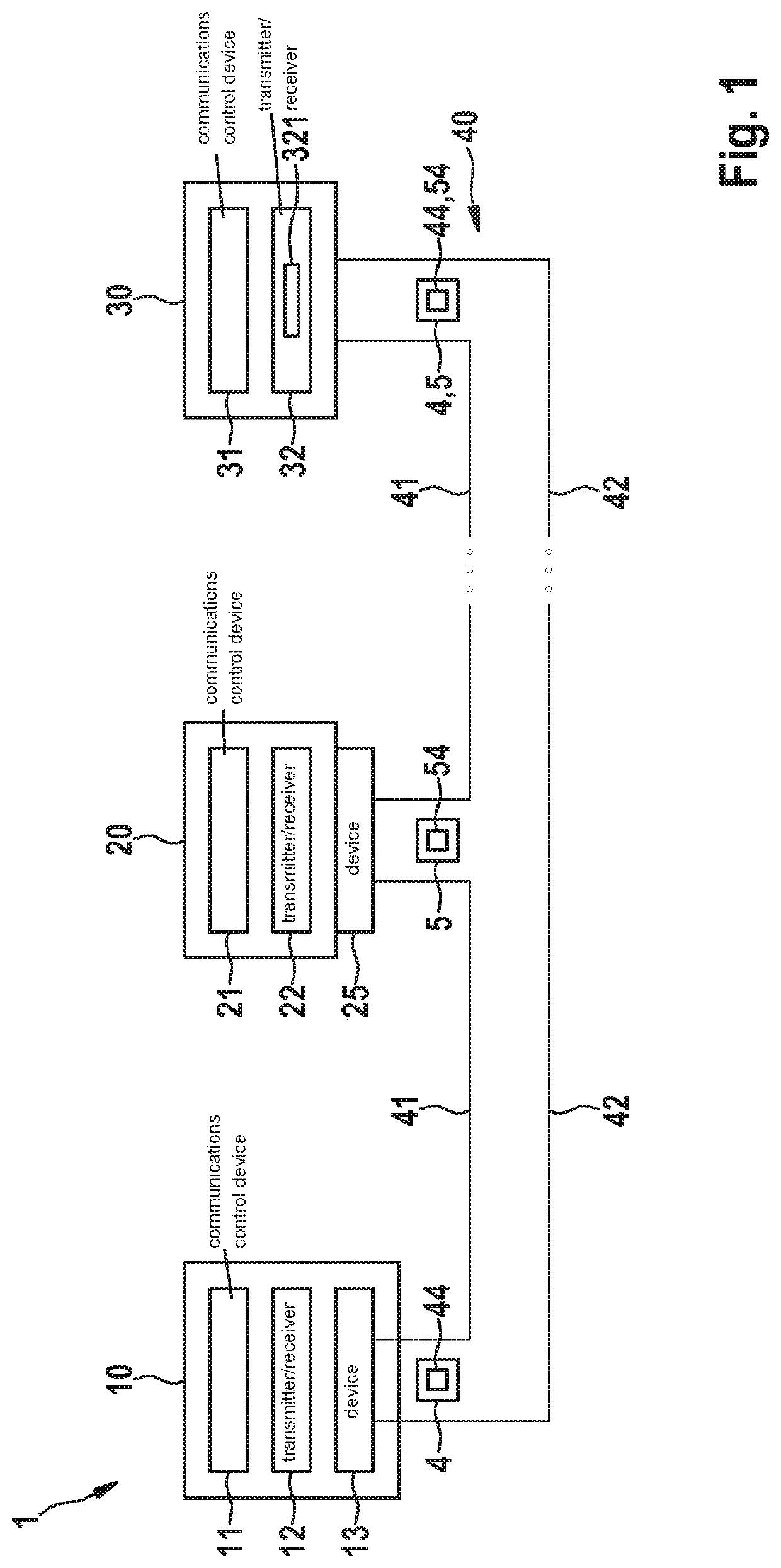
[0039]FIG. 1 shows a bus system 1, which, for instance, is at least partly a bus system in which at least one bus state or voltage state is actively driven. Such a bus system 1 is particularly a CAN bus system, a CAN-FD bus system, etc., to which reference is made in the following text in order to describe the principle of the present invention. Bus system 1 can be used in a vehicle, in particular a motor vehicle, an airplane, etc. or in a hospital, etc. However, bus system 1 is not restricted to such a use. In general, bus system 1 is any serial bus system in which a bit asymmetry may occur under real operating conditions, in which the time period of a dominant bus state differs from the time period of a recessive bus state.

[0040]In FIG. 1, bus system 1 has a multitude of user stations 10, 20, 30, each being connected to a bus 40 by a first bus wire 41 and a second bus wire 42. In a CAN bus system, bus wires 41, 42 are also called CAN_H and CAN_L and are used for the electrical sig...


PUM


Abstract

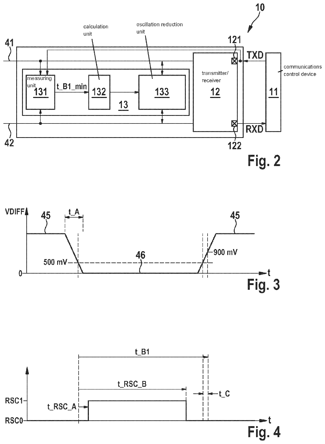
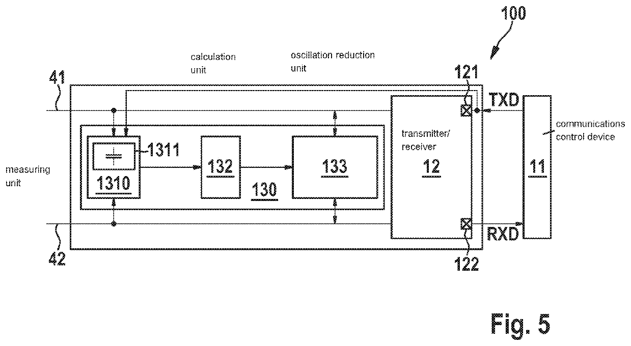
A device and a method for a transmitter / receiver device of a bus system are provided. The device has a measuring unit for measuring a minimum recessive bit time that occurs during an operation of the bus system in a message received by the device from a bus of the bus system, a voltage state of the message having been actively driven by a transmitter / receiver device of one of at least two user stations of the bus system; a calculation unit for calculating a power-on period on the basis of the minimum recessive bit time supplied by the measuring unit, the power-on period being a time period for which an oscillation reduction unit is to be switched on, which is used for reducing oscillations on the bus that occur after a transition between different voltage states of a bus signal transmitted on the bus.

Description

[0001]The present invention relates to a device and to a method for a transmitter / receiver device of a bus system. The device and the method are developed in such a way that a power-on period for a function by which a reduction of the oscillation tendency during a transition between different bit states of a bus signal is achievable is dynamically adaptable.BACKGROUND INFORMATION[0002]In a message or data transmission in a bus system, information included in bytes or bits of the messages or data is represented by different bit states or voltage states. The different bit states entail different bus states during the transmission of the message via a bus of the bus system. Depending on the bus system, different transmission protocols exist for a message or data transmission.[0003]In the CAN bus system, for example, messages are transmitted using the CAN and / or CAN FD protocol as it is described in the ISO-11898-1:2015 standard as the CAN protocol specification with CAN FD. At present,...

Claims


Application Information

Patent Timeline
IPC IPC(8): H04L12/40
CPCH04L12/40032H04L12/40013H04L2012/40241H04L12/4015H04L2012/40215H04L12/40084H04L12/40039H04L2012/40273
Inventor MUTTER, ARTHUR
Owner ROBERT BOSCH GMBH
Learn More