High frequency apparatus
- Summary
- Abstract
- Description
- Claims
- Application Information
AI Technical Summary
Benefits of technology
Problems solved by technology
Method used
Image
Examples
first embodiment
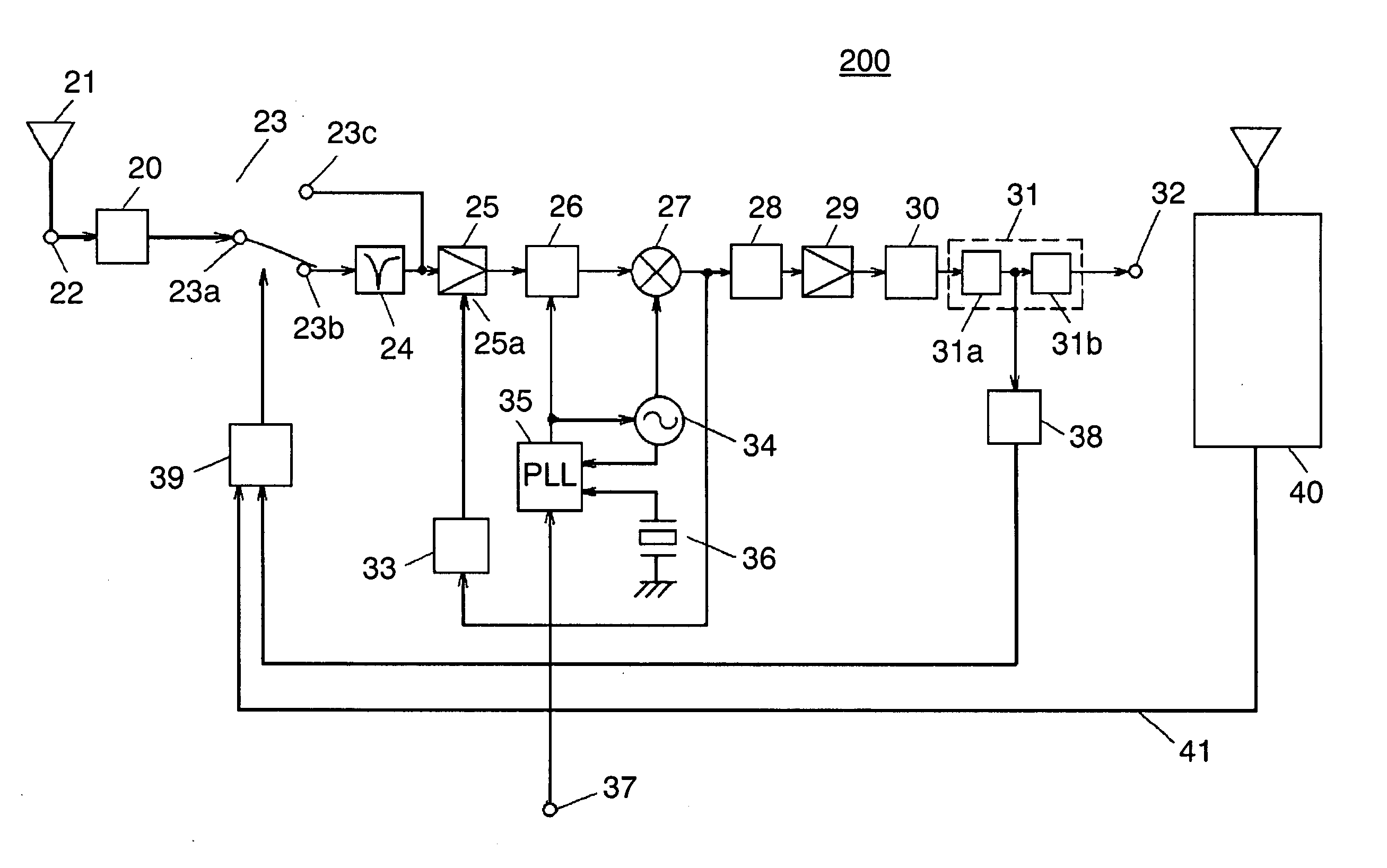
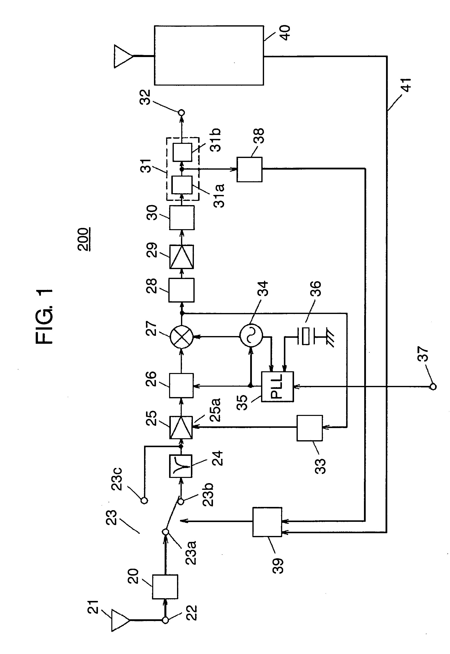
[0018]FIG. 1 is a block diagram of high frequency apparatus 200 according to the first embodiment of this invention. High frequency apparatus 200 of the first embodiment is suitable for removing interfering signals anticipated in advance as being exist in a given frequency band. This is based on a concept that the frequency band of undesirable signals output and transmitted by a cellular telephone is either known or foreseeable when, for instance, the cellular telephone is built in and mounted to high frequency apparatus 200.
[0019] In FIG. 1, high frequency apparatus 200 comprises input terminal 22 connected to antenna 21, and input filter 20 connected to input terminal 22. Apparatus 200 also comprises selector switch 23 having common terminal 23a in connection to an output of input filter 20, and interference-cut filter 24 connected to one side terminal 23b of selector switch 23 for the purpose of removing interfering signals. Apparatus 200 also comprises AGC amplifier 25 for rece...
second embodiment
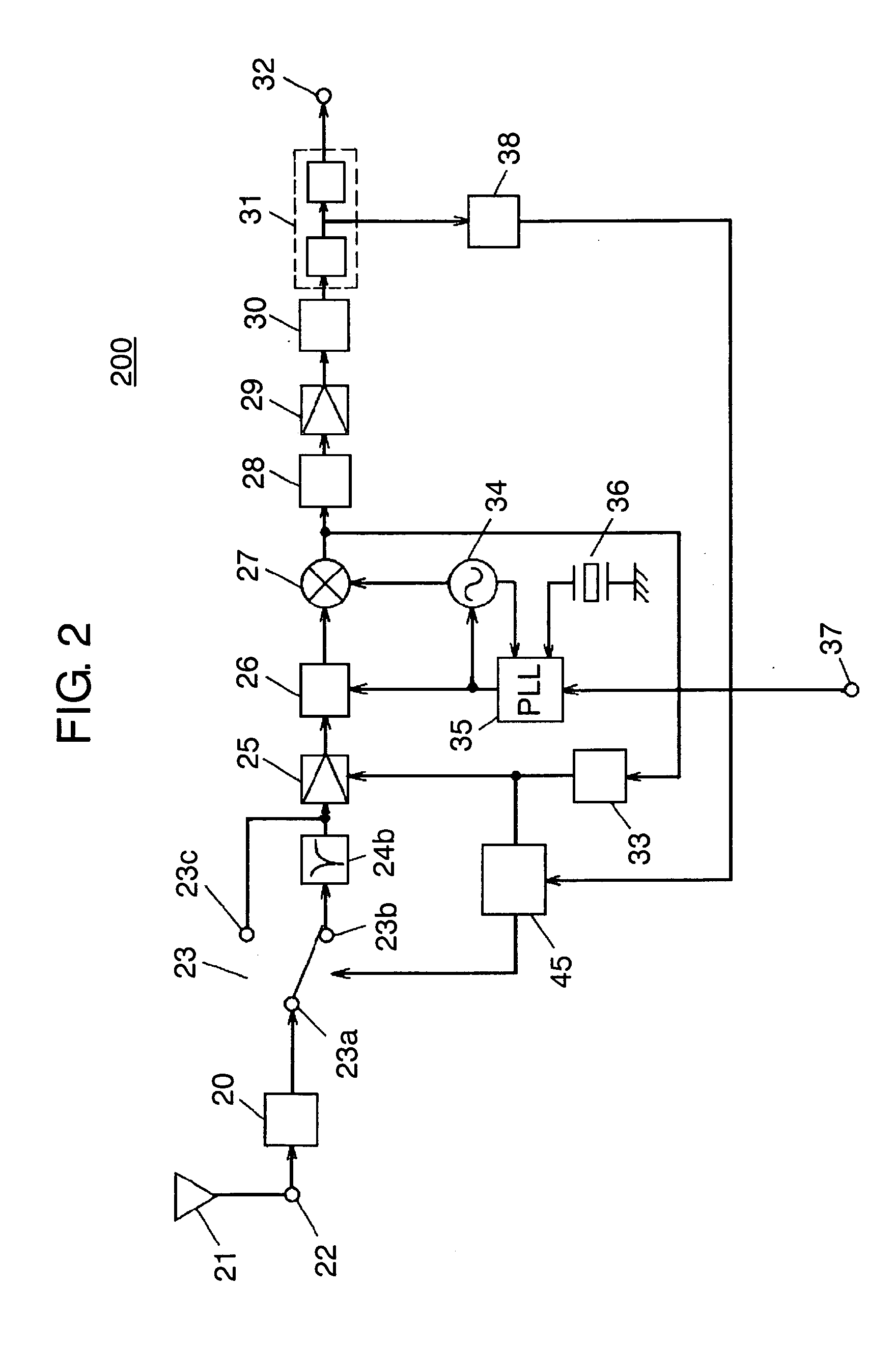
[0039]FIG. 2 is a block diagram of high frequency apparatus 200 according to the second embodiment of this invention. High frequency apparatus 200 described in this second embodiment is also intended to separate interfering signals of an anticipated frequency band, and to exclude them from the originally desired normal signals. One such example is the case in which analog broadcasting signals of 6 channel or 8 channel may exist as interfering signals when receiving digital broadcasting signals of the adjacent 7 channel.
[0040] In this instance, interference-cut filter 24b having a center frequency (any of 6 and 8 channels) is proved effective for the pre-determinate interference frequency (6 or 8 channels) input to antenna 21 from the outside.
[0041] The second embodiment is contrived to control selector switch 23 when there is a large input of interfering signals, and if the originally desired signals output from mixer 27 have a small amplitude. In the second embodiment, like refer...
third embodiment
[0045]FIG. 3 is a block diagram of high frequency apparatus 200 according to the third embodiment of this invention. High frequency apparatus 200 of this third embodiment is also proved effective when interfering signals exist in an anticipated frequency band. One such example is the case in which there is a manufactory and the like facility in the vicinity of a location where high frequency apparatus 200 of this invention is used, and emission of interfering signals is anticipated from there. Moreover, this embodiment is particularly effective when a frequency band of the interfering signals is known or foreseeable. Like reference marks are used to designate the like components as those of the first and second embodiments, and their descriptions will be abbreviated.
[0046] In FIG. 3, interference-pass filter 46a for passing interference frequency is connected to input terminal 22, and interfering signal detector 47 is connected between an output of interference-pass filter 46a and ...
PUM
 Abstract
Description
Claims
Application Information
 - R&D
- Intellectual Property
- Life Sciences
- Materials
- Tech Scout
- Unparalleled Data Quality
- Higher Quality Content
- 60% Fewer Hallucinations
Browse by: Latest US Patents, China's latest patents, Technical Efficacy Thesaurus, Application Domain, Technology Topic, Popular Technical Reports.
© 2025 PatSnap. All rights reserved.Legal|Privacy policy|Modern Slavery Act Transparency Statement|Sitemap|About US| Contact US: help@patsnap.com


