
Locking system for a door

a locking system and door technology, applied in the field of trailer security systems, can solve the problems of lack of effective security systems, easy for thieves to break into, and lock mechanisms, and achieve the effects of improving trailer security, simple, convenient and inexpensive, and improving safety

Inactive Publication Date: 2005-08-02
CALDWELL WILLIAM J +1
View PDF24 Cites 19 Cited by
  • Summary
  • Abstract
  • Description
  • Claims
  • Application Information

AI Technical Summary

Benefits of technology

"The present invention provides a better and more secure device for locking the door of a trailer. It is a simple, convenient, and inexpensive solution that increases trailer security. The locking bar is guided and secured by two guides which are mounted in a horizontal orientation using bolts to the interior of the trailer door. The locking bar may be raised and lowered into the desired position by means of a toggle mechanism. The toggle mechanism is turned using a common trailer latch that also locks (secondary) by use of a key. The use of a remote is particularly useful where there is a source of power, such as a battery, available on the trailer or a truck that is used to pull the trailer. To open, insert key in the key entry and pull the hardened key pin out. Then, you may raise the locking bar above the trailer floor by turning the trailer latch to the open position which is the opposite direction from which the bar was lowered."

Problems solved by technology

The disadvantage of the outside-style lock is that it is easy for thieves to break by cutting the lock or lock hasps.
Owners of trailers try the methods described above because of the lack of effective security systems.
The locking mechanism is hidden underneath the trailer and is virtually impossible to remove with ordinary tools that thieves may have in their possession.

Method used


Image

  • Locking system for a door
  • Locking system for a door
  • Locking system for a door

Examples


Embodiment Construction

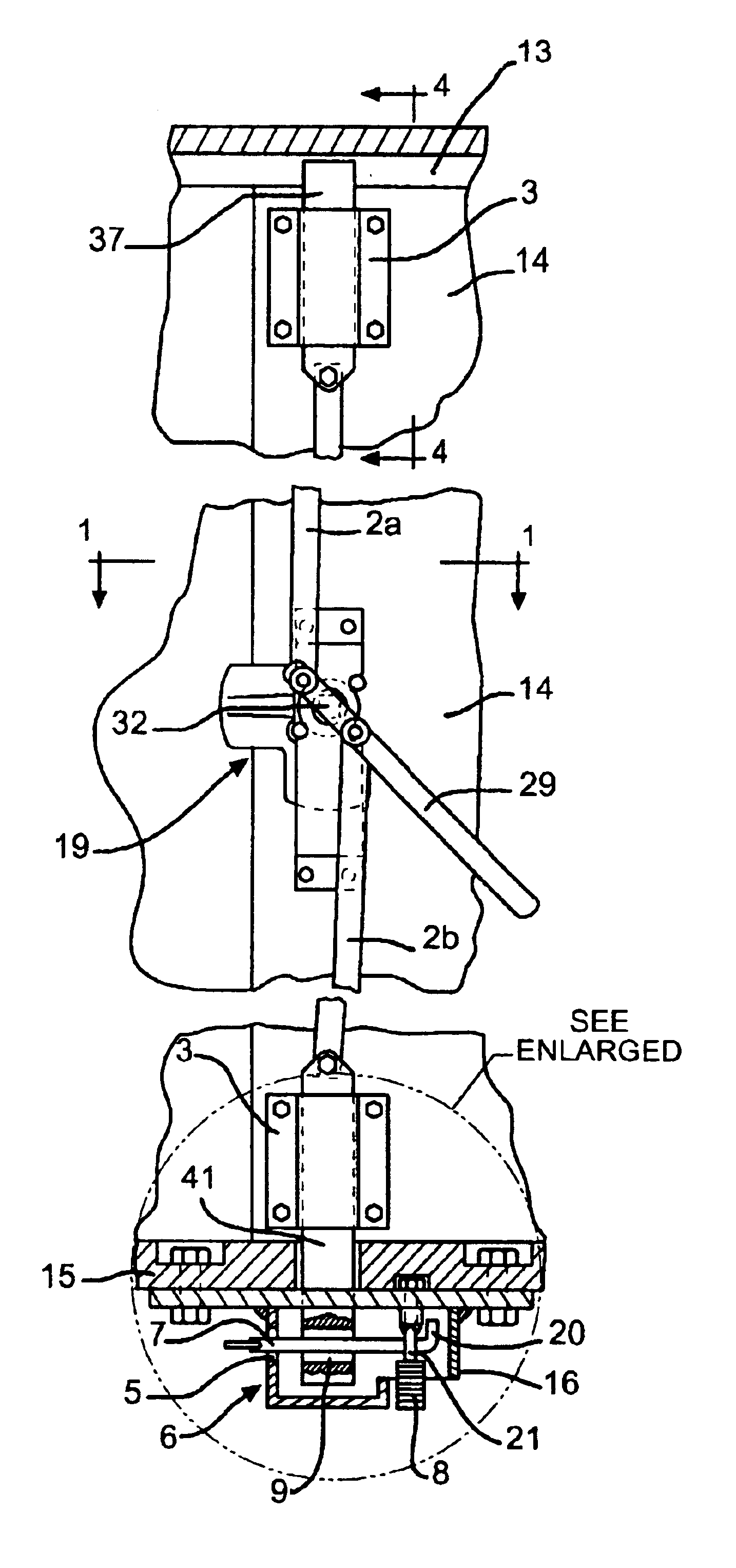
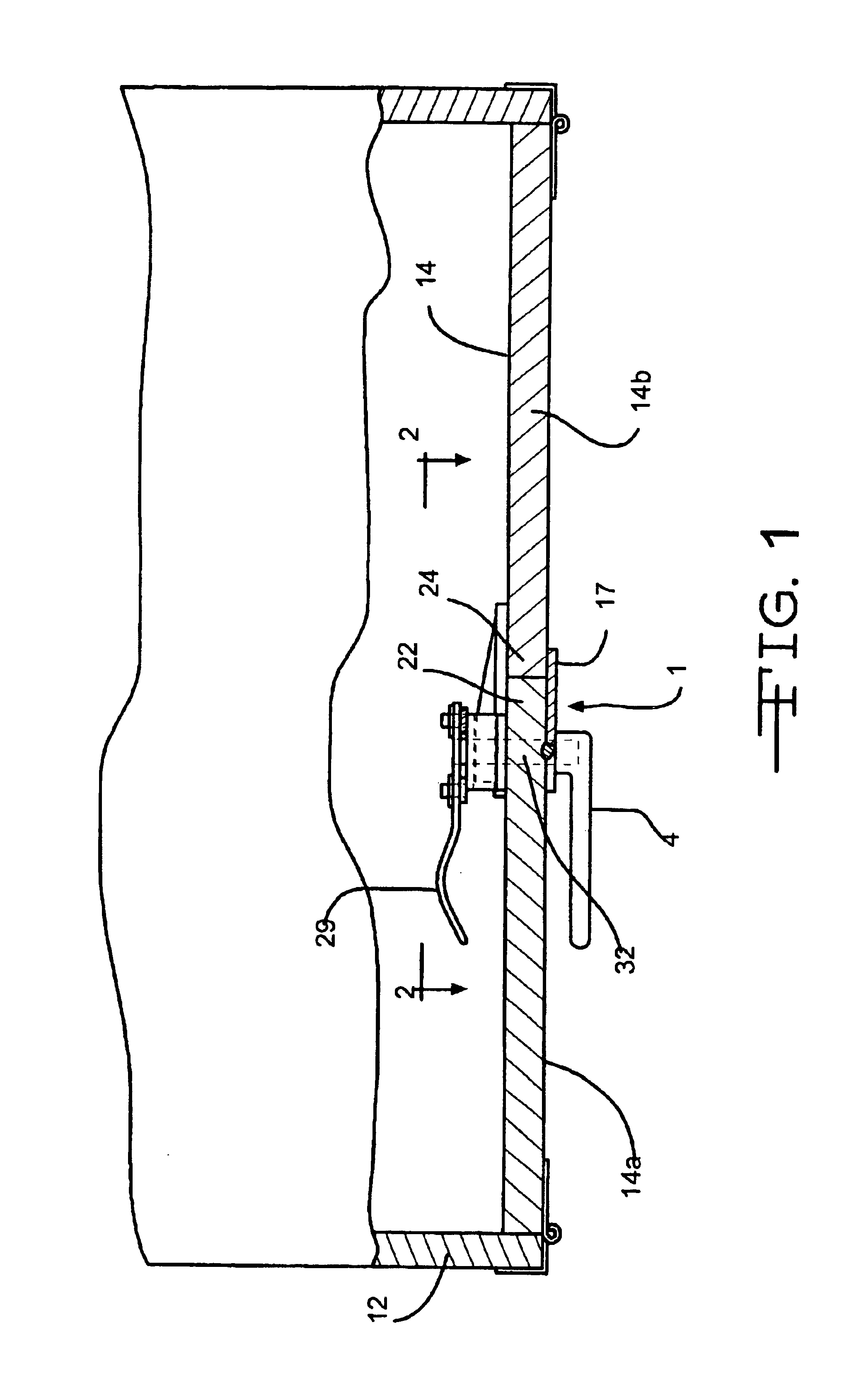
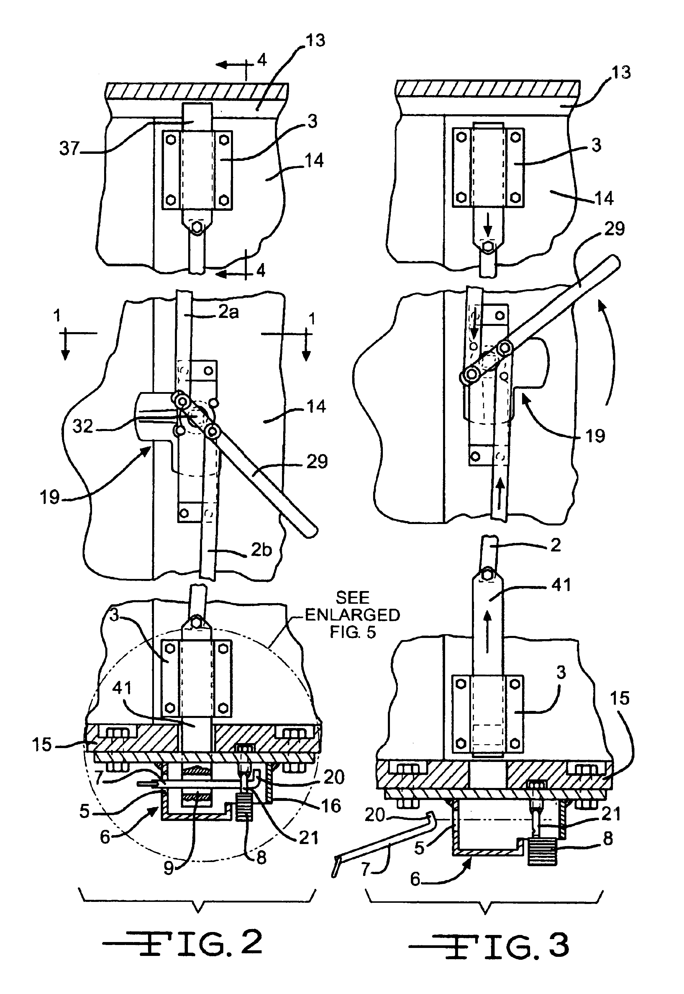
[0014]As seen in FIGS. 1-5 the invention is a trailer locking system 1 having a locking bar 2 which is secured and guided by two guides 3 which are installed in a horizontal orientation using bolts to the inside of the trailer door 14. The trailer door 14 has a first section 14a and a second section 14b that are pivotally mounted to one end of a trailer 12. The locking system 1 is positioned on the first section 14a of the trailer door 14. The first section 14a has a flange 17 that extends from the edge 22 of the first section 14a and is disposed to overlap the edge 24 of the second section 14b. The flange 17 is positioned so that it overlaps the second section 14b when the door 14 is in the closed position as shown in FIG. 1. With this arrangement, if the first section 14a is in a locked position, the flange 17 will overlap the second section 14b and prevent the second section from being opened.

[0015]The locking bar 2 has a first end 2a and a second end 2b that are connected to the...


PUM


Abstract

A security locking system for trailers that features an interior locking bar that is controlled from the outside. The locking bar is traversed in a linear motion parallel to the door by a toggle mechanism. The bar is guided into the locking mechanism by two guides mounted to the inside of the trailer door. The toggle mechanism is turned using a common trailer latch that also locks by use of a key. Alternatively the latch could be modified to lock or unlock by using a remote activator. Once the latch is turned all the way (90 degrees) it will raise the locking bar into the upper secure bracket. The lower part of the locking bar will be lowered into the lock housing which is hidden just under the trailer floor, it will then be in position in the locking mechanism for the key pin to be inserted and then locked. The locking mechanism can also be modified to be controlled using a remote activator.

Description

BACKGROUND OF THE INVENTION[0001]The use of locks on the outside of trailer doors is known and typical. Regardless of the type of trailer from the smallest to the large tractor trailers, the method of securing the trailer is basically the same and needs to be improved. The disadvantage of the outside-style lock is that it is easy for thieves to break by cutting the lock or lock hasps. To limit access to a trailer's contents, owners of trailers will commonly back up heavy equipment against the trailer door when they leave the trailer. Tractor trailers occasionally will be backed up to a wall when left overnight. Owners of trailers try the methods described above because of the lack of effective security systems.[0002]The present invention relates to a trailer security system that features an interior locking bar operated from the outside of the trailer. The locking mechanism is hidden underneath the trailer and is virtually impossible to remove with ordinary tools that thieves may ha...

Claims


Application Information

Patent Timeline
Patent Type & Authority Patents(United States)
IPC IPC(8): E05B15/00E05B47/06E05B15/12E05B67/38E05C9/00E05B65/12E05B67/00E05B65/16E05C9/04
CPCE05B17/2023E05B47/0696E05C9/048E05B77/44E05B67/383E05B83/12Y10S292/32Y10T70/498Y10T70/5199Y10T70/5319Y10T70/5739Y10T70/577Y10T70/5779Y10T292/1025Y10T292/1028
Inventor CALDWELL, WILLIAM J.CALDWELL, WILLIAM D.
Owner CALDWELL WILLIAM J
Learn More