Supercharge Your Innovation With Domain-Expert AI Agents!

Dual height airspring having adjusted spring rate

a technology of air spring and spring rate, which is applied in the field of air springs, can solve the problems of reducing the spring rate of air springs well beyond the capability, and achieve the effects of high spring rate, high spring height, and low spring ra

Inactive Publication Date: 2005-08-02
VEYANCE TECH
View PDF10 Cites 16 Cited by
  • Summary
  • Abstract
  • Description
  • Claims
  • Application Information

AI Technical Summary

Benefits of technology

"The patent describes an air spring that has two different heights and can adjust its spring rate by inflating a bladder inside it. This allows the air spring to provide a low spring rate at lower heights and a high spring rate at higher heights. The technical effect of this design is that it allows for a more stable and comfortable ride for vehicles and other systems that use air springs."

Problems solved by technology

This additional internal air volume, however, greatly reduces the spring rate of the air spring well beyond the capability of design tools such as piston tapering or other air spring shaping to correct.

Method used


Image

  • Dual height airspring having adjusted spring rate
  • Dual height airspring having adjusted spring rate
  • Dual height airspring having adjusted spring rate

Examples


Embodiment Construction

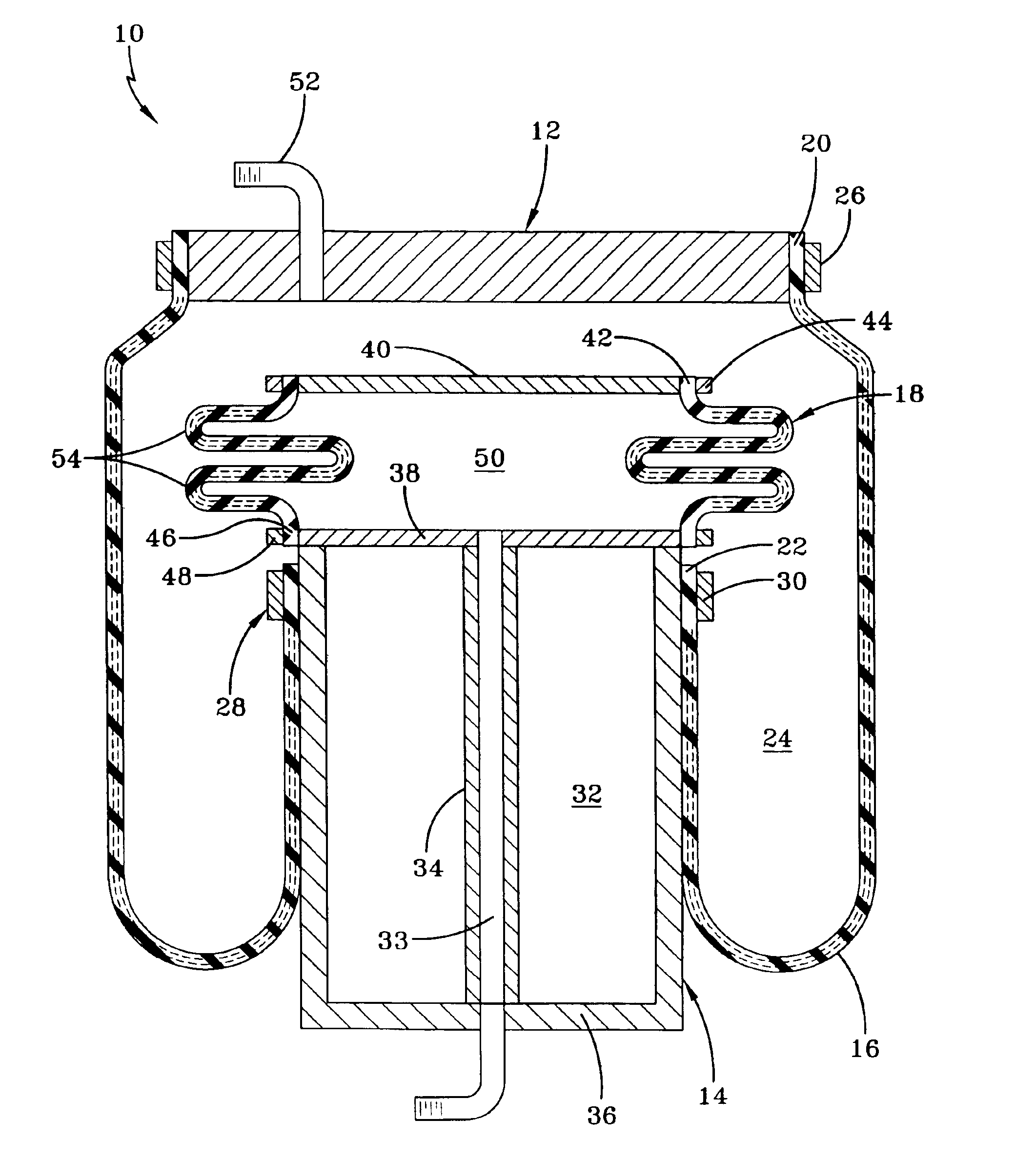
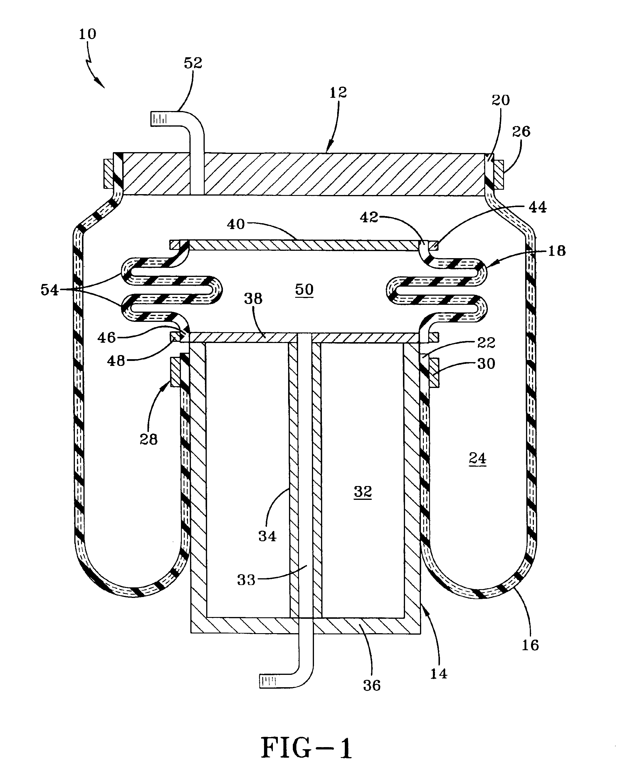
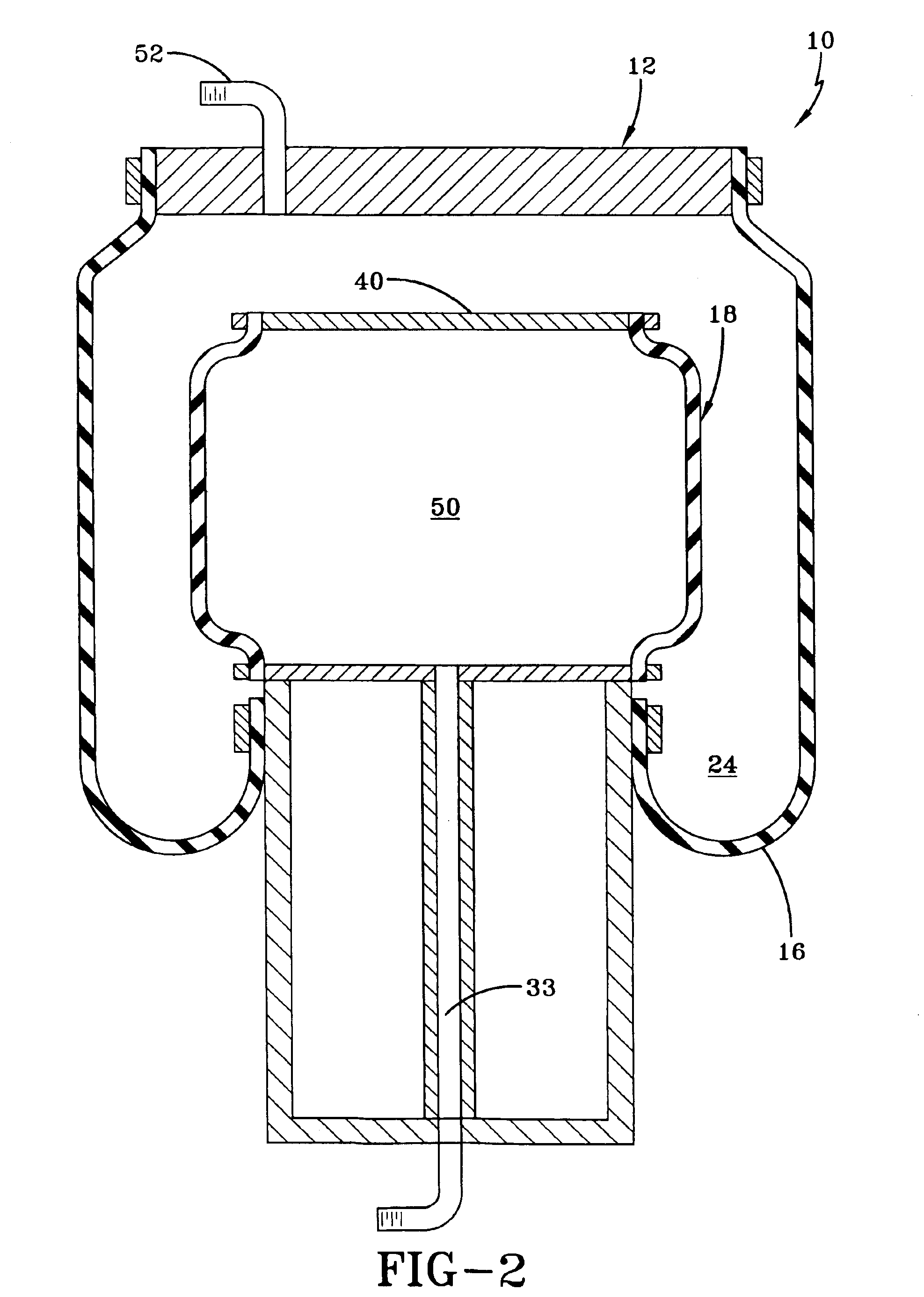
[0013]FIG. 1 illustrates the inventive air spring 10. The air spring 10 has four main components: the upper retainer 12, the piston 14, the elastomeric sleeve 16, and the internal bladder 18. The elastomeric sleeve 16 is secured at first end 20 to the upper retainer 12 and to the piston 14 at the opposing end 22, forming a chamber 24.

[0014]The elastomeric sleeve 16 is preferably comprised of at least 3 plies: an outer elastomeric ply, at least one reinforcing ply formed of elastomeric embedded reinforcing cords, and an inner elastomeric ply. In the illustrated sleeve 16, upper end 20 of the sleeve 16 is secured onto the upper retainer 12 by means of a clamping ring 26 in a conventional manner, similar to that disclosed in U.S. Pat. No. 5,005,808. Alternatively, the upper sleeve end 20 may have an inextensible bead about which the upper retainer 12 is crimped for securing the sleeve end 20, similar to those disclosed in U.S. Pat. No. 5,535,994 or 5,580,033. Similarly, the lower sleev...


PUM


Abstract

An air spring having a relatively low and a relatively high spring height includes a retainer, a base housing, an elastomeric sleeve secured to the retainer at a first end and secured to the base housing at a lower end to form a chamber, the elastomeric sleeve expanding from a relatively collapsed configuration at the low air spring height into an expanded configuration at the high air spring height. A confined bladder is disposed within the chamber, the bladder being inflatable to displace a variable portion of an expanded volume within the sleeve chamber at the high air spring height. The spring rate of the air spring is adjusted by an adjustment to the volume of air displaced by the inflated bladder within the sleeve chamber and by overpressurizing the bladder relative to the air spring sleeve, whereby the air spring is adapted to provide a relatively low spring rate at the lower height and a relatively high spring rate at the higher height.

Description

FIELD OF THE INVENTION[0001]The present invention relates generally to air springs and, in particular, to a height and spring rate adjustable air spring.BACKGROUND OF THE INVENTION[0002]Air springs are in common use for motor vehicles and various machines and other equipment. The springs are designed to support a suspension load such as a vehicle. The springs are often combined with a separate shock absorber device in the suspension that functions to dampen oscillations. Air springs typically consist of a flexible elastomeric reinforced sleeve that extends between a pair of end members. The sleeve is attached to end members to form a pressurized chamber therein. The end members mount the air spring on spaced components or parts of the vehicle or equipment on which the air spring is to be mounted.[0003]The internal pressurized gas, usually air, absorbs most of the motion impressed upon or experienced by one of the spaced end members by which the air spring is mounted. The end members...

Claims


Application Information

Patent Timeline
Patent Type & Authority Patents(United States)
IPC IPC(8): F16F9/05F16F9/02F16F9/04B60G7/04B60G17/005B60G17/048
CPCB60G7/04B60G11/27B60G17/005B60G17/0485B60G17/0521F16F9/05B60G2204/45B60G2204/4605
Inventor SCHISLER, ROBERT CHARLES
Owner VEYANCE TECH
Features
  • R&D
  • Intellectual Property
  • Life Sciences
  • Materials
  • Tech Scout
  • Unparalleled Data Quality
  • Higher Quality Content
  • 60% Fewer Hallucinations
Learn More