Strut suspension system with dual-path top mounts

a suspension system and top mount technology, applied in the direction of shock absorbers, mechanical equipment, transportation and packaging, etc., can solve the problems of increasing the effective reducing the axial length of the suspension, and difficult to reduce the offset x, so as to improve the driving stability, avoid interference, and improve the lateral rigidity of the stru

Inactive Publication Date: 2005-08-02
MITSUBISHI MOTORS CORP
View PDF15 Cites 37 Cited by
  • Summary
  • Abstract
  • Description
  • Claims
  • Application Information

AI Technical Summary

Benefits of technology

[0038]This makes it possible to have the axis of rotation of the bearing and the king pin axis coincided with each other by the extremely simple measure that the lower bracket is changed in configurations.
[0039]Preferably, the lower bracket may be configured to have, on a contact portion thereof with the insulator, a plane lying at a right angle to a strut axis and, on a bearing support portion thereof for the bearing, a plane lying at a right angle to the king pin axis. This makes it possible to bear damping force of the shock absorber, downward force, in the direction of the strut axis by the lower bracket, a single part, alone. In addition, this also makes it possible to bear force from the second input system in the direction of the king pin axis.
[0040]The lower bracket may preferably be provided on an outer circumference of the insulator contact portion thereof with the bearing support portion. This makes it, possible to avoid interference between the insulator and the bearing even when they are arranged at the same height in the direction of an axis of the strut. This also makes it possible to use conventional parts as members other than the lower bracket, such as the insulator and the bearing.
[0041]Preferably, the strut suspension system with dual-path top mounts may further comprise a bump rubber arranged on an outer circumference of the piston rod, and the bump rubber may be disposed below the insulator with only the lower bracket interposed therebetween. This makes it possible to arrange the bump rubber at a still higher level and hence to set the strut shell longer. Accordingly, the lateral rigidity of the strut can be improved, contributing to improvements in driving stability.
[0042]The bump rubber may preferably be at an upper end thereof in contact at an upper end thereof with a plane which lies at a right angle to the strut axis at the contact portion of the lower bracket with the insulator. This allows the bump rubber to adequately exhibit its bump stopper effect along the direction of plunger extensions and contractions of the shock absorber.

Problems solved by technology

This moment acts as a cause of a deflection of a vehicle and has posed a problem.
This, however, requires extremely difficult work that the positioning of the upper force application point 1 is performed in the manufacturing process.
Therefore it is not easy to reduce the offset x.
This arrangement is, however, disadvantageous in decreasing the axial length of the suspension and increasing the effective length of the suspension.

Method used


Image

  • Strut suspension system with dual-path top mounts
  • Strut suspension system with dual-path top mounts
  • Strut suspension system with dual-path top mounts

Examples


Embodiment Construction

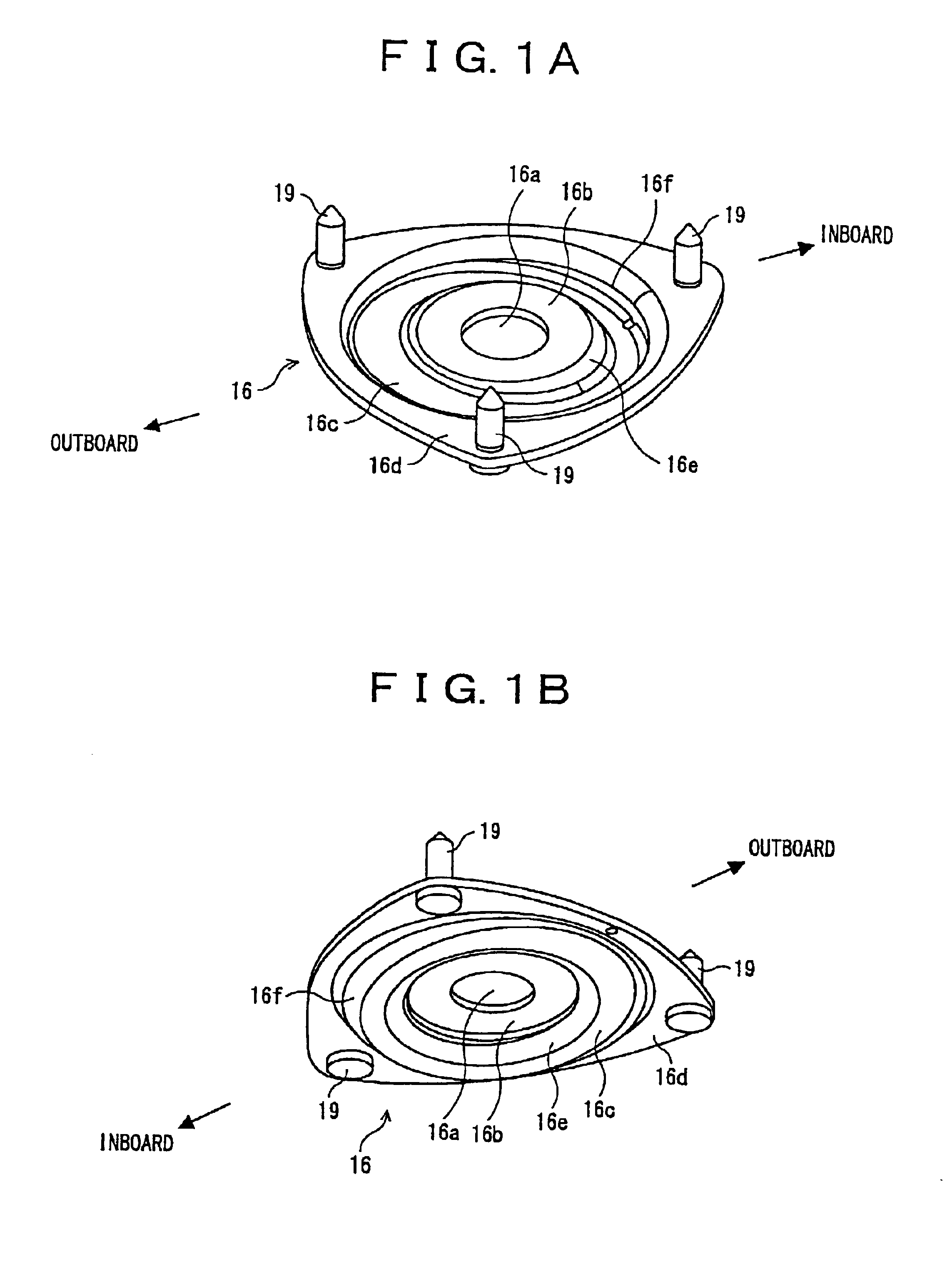
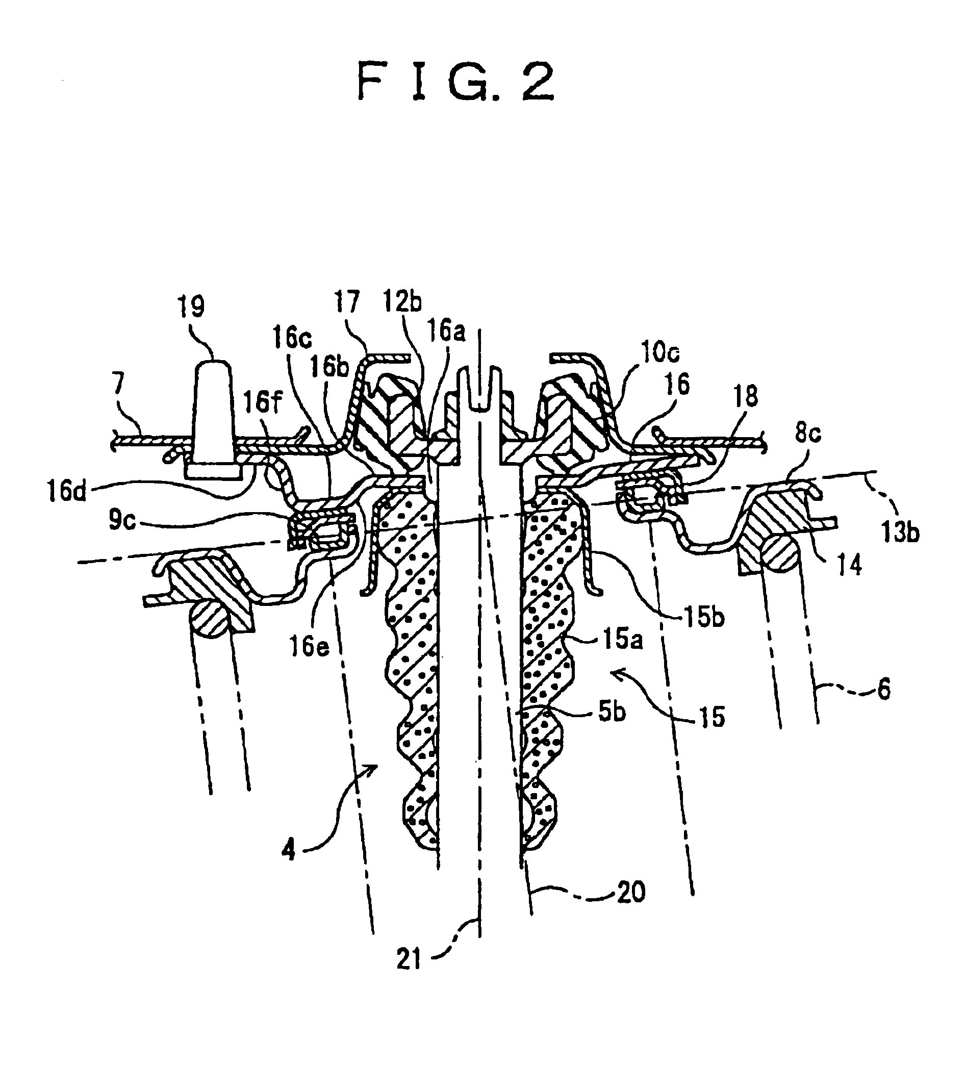
[0051]With reference FIGS. 1A, 1B and 2 of the accompanying drawings, a description will hereinafter be made about the embodiment of the present invention. Reference will also be had to FIG. 3 in some of the description, because the construction of a lower part of this suspension system is similar to that of the conventional suspension system shown in FIG. 3.

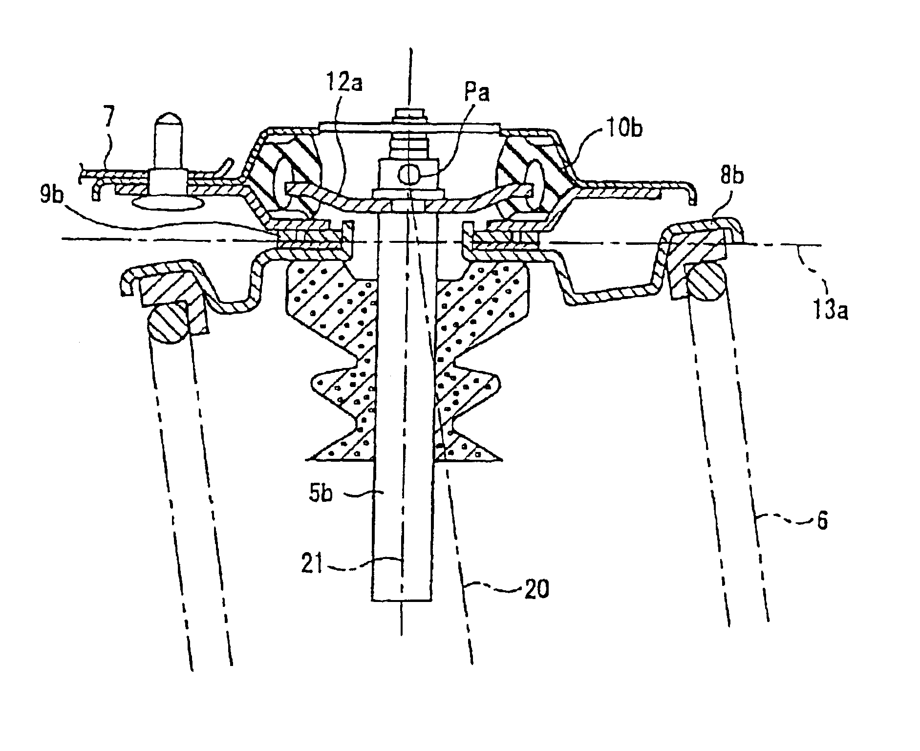
[0052]The strut suspension system with dual-path top mounts according to this embodiment is used to suspend a steered wheel. As illustrated in FIG. 3, a knuckle 2 connected to a wheel 1 via a bearing is connected to a vehicle body 7 via a lower arm 3 and a strut 4. The lower arm 3 connects a lower part 2A of the knuckle 2 to the vehicle body 7. The strut 4 is provided with a shock absorber 5 which has a cylinder tube 5a and a piston rod 5b. Around the shock absorber 5 via which an upper part 2B of the knuckle 2 is connected to the vehicle body 7, a coil spring 6 is arranged. The cylinder tube 5a is connected at a lower end porti...


PUM


Abstract

A strut suspension system with dual-path top mounts is provided with a first input system and a second input system. In the first input system, an upper part of a piston rod (5a) of a shock absorber (5) arranged on a strut (4) is connected to a vehicle body (7) via an insulator (10c) when the strut suspension system is arranged on an automotive vehicle. In the second input system, an upper part of a coil spring (6) arranged on an outer circumference of the strut (4) is connected to the side of the vehicle body (7) via an upper spring seat (8c) and a bearing (9c) when the strut suspension system is arranged on the automotive vehicle. To permit suppressing deflection of the vehicle by reducing a total steer moment applied to the suspension system without resulting in an increase in the number of parts, a lower bracket (16) is arranged in contact with a lower surface of the insulator (10c) and between the bearing (9c) and the vehicle body (7), and is formed such that the lower bracket downwardly extends to greater extent on an inner side thereof as viewed in a lateral direction of the vehicle (7) than on an outer side thereof to have an axis of rotation of the bearing and a king pin axis (20) coincided with each other (FIG. 2).

Description

[0001]This application is the national phase under 35 U.S.C. § 371 of PCT International Application No. PCT / JP01 / 09903 which has an International filing date of Nov. 13, 2001, which designated the United States of America.TECHNICAL FIELD[0002]This invention relates to a strut suspension system with dual-path top mounts, in which an upper part of a strut and an upper part of a coil spring are connected to a vehicle body independently from each other.BACKGROUND ART[0003]Strut suspension systems for automobiles are used to suspend steered wheels and include, for example, one having such a structure as illustrated in FIG. 3. In this strut suspension system, a knuckle 2 connected to a wheel 1 via a bearing is connected to a vehicle body 7 by a lower arm 3 and a strut 4.[0004]As is illustrated in FIG. 3, the strut 4 is provided with a shock absorber 5 having a cylinder tube 5a and a piston rod 5b, and a coil spring 6 is arranged around the shock absorber 5. The cylinder tube 5a is connect...

Claims


Application Information

Patent Timeline
Patent Type & Authority Patents(United States)
IPC IPC(8): B60G15/06B60G15/00F16F9/54F16F9/58
CPCB60G15/063B60G15/068F16F9/54F16F9/58B60G2200/46B60G2202/312B60G2204/124B60G2204/128B60G2204/418B60G2204/43B60G2204/44B60G2204/4502B60G2204/61B60G15/07
Inventor MOMOSE, NOBUONIINA, YUZO
Owner MITSUBISHI MOTORS CORP
Why Eureka
Try Eureka