
Coil stop for rail road coil car

a coil car and rail road technology, applied in the field of rail cars, can solve the problems of limited lading total width that can be carried by a coil car at one time, heavy top and bottom flanges of the main center sill,

Inactive Publication Date: 2005-08-02
NATIONAL STEEL CAR
View PDF74 Cites 10 Cited by
  • Summary
  • Abstract
  • Description
  • Claims
  • Application Information

AI Technical Summary

Benefits of technology

The patent describes a railroad coil car that has a trough structure for carrying coils. The trough structure includes first and second side sills and a beam member spanning the trough structure. The coil car also has a walkway for easy movement of personnel and a cover for sheltering the coils. The trough structure has a longitudinally oriented first trough and a second trough with a valley bottom and a second walkway. The coil car falls within a design envelope width limit of 128 inches. The technical effects of the invention include improved load capacity, improved safety, and better protection of coils during transportation.

Problems solved by technology

The top and bottom flanges of the main center sill tend to be very heavy in such cars, since they are relied upon to carry the vertical bending load.
First, the total width of lading that can be carried by a coil car at one time is limited by the allowable car width envelope.

Method used


Image

  • Coil stop for rail road coil car
  • Coil stop for rail road coil car
  • Coil stop for rail road coil car

Examples


Embodiment Construction

[0062]The description that follows, and the embodiments described therein, are provided by way of illustration of an example, or examples of particular embodiments of the principles of the present invention. These examples are provided for the purposes of explanation, and not of limitation, of those principles and of the invention. In the description that follows, like parts are marked throughout the specification and the drawings with the same respective reference numerals. The drawings are not necessarily to scale and in some instances proportions may have been exaggerated in order more clearly to depict certain features of the invention.

[0063]In terms of general orientation and directional nomenclature, for each of the rail road cars described herein, the longitudinal direction is defined as being coincident with the rolling direction of the car, or car unit, when located on tangent (that is, straight) track. In the case of a car having a center sill, whether a through center sil...


PUM


Abstract

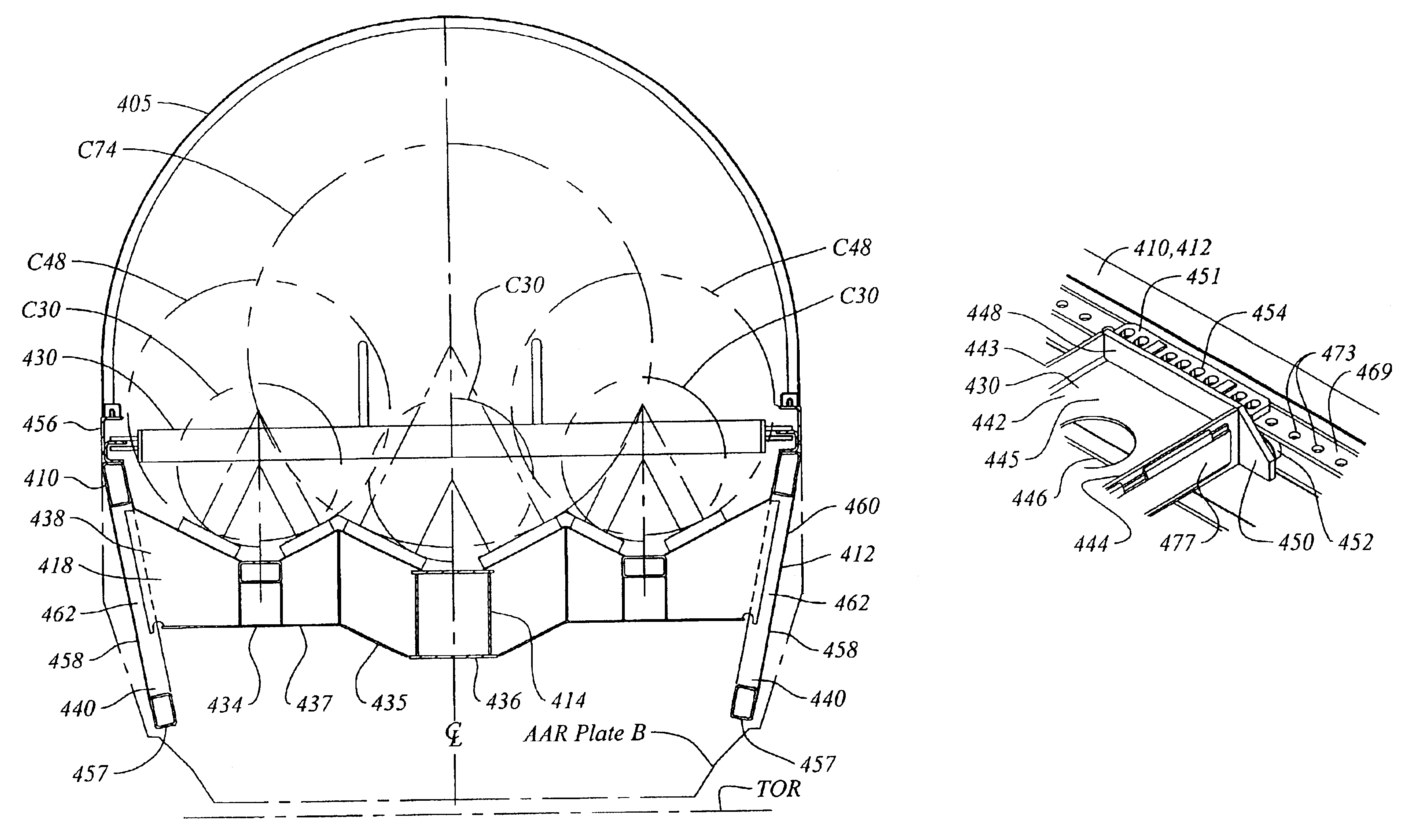
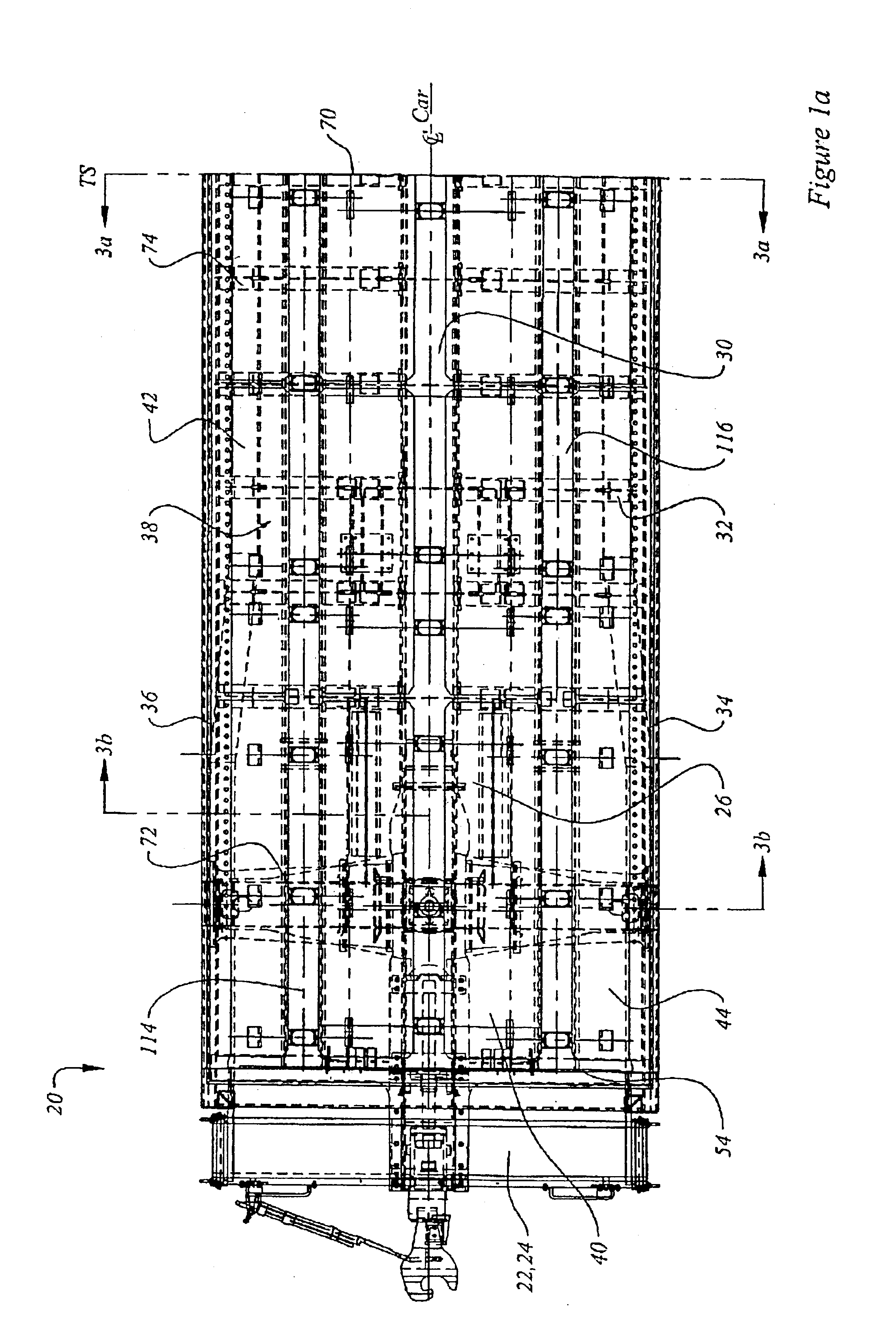
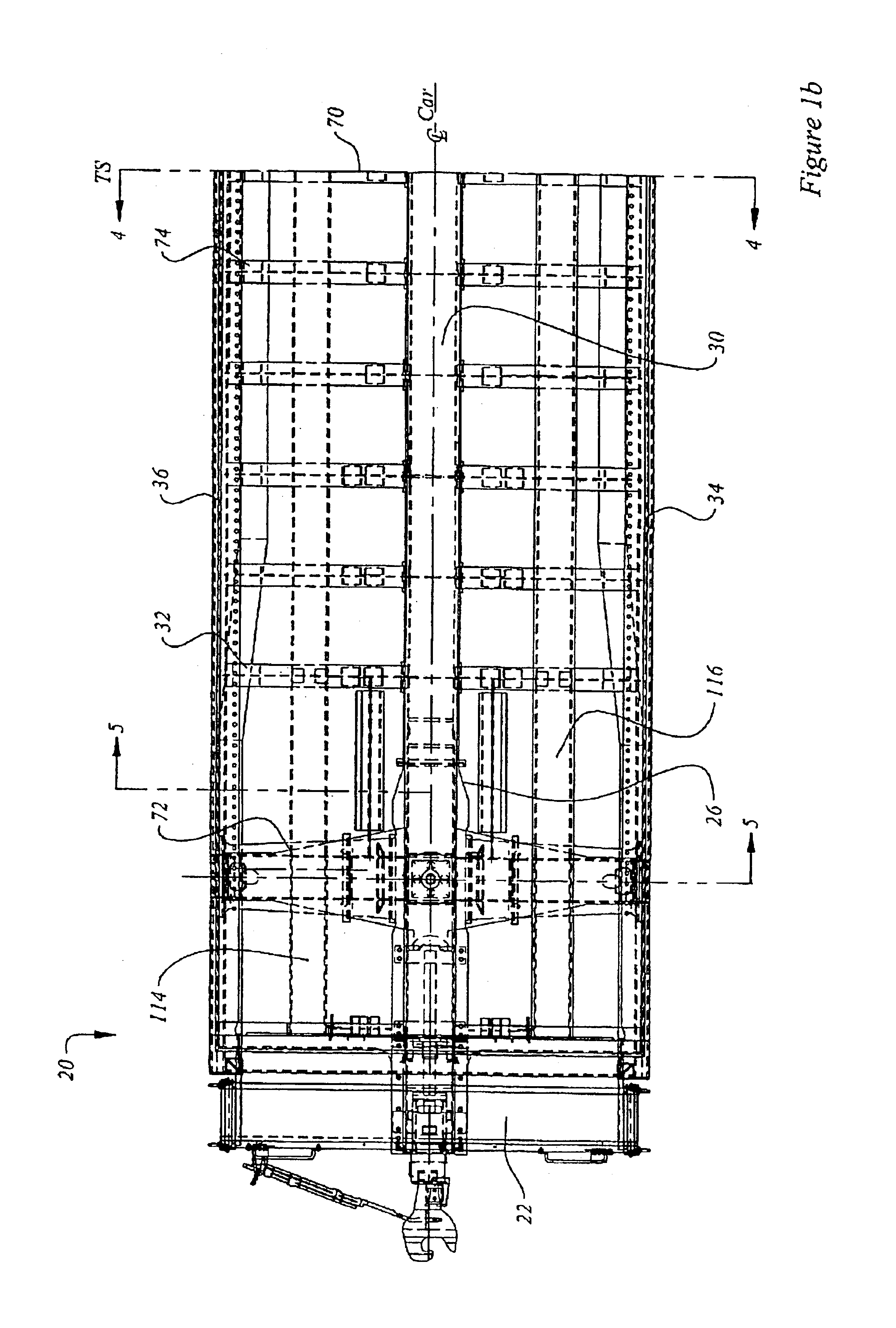
A coil car has a pair of deep side sills and a trough structure mounted to, and suspended between, the deep side sills for carrying coils. The side sills extend between the rail car trucks and act as a pair of deep side beams for carrying vertical loads. The deep side sills are arranged to extend above and below the center sill of the coil car to give vertical stiffness to the coil car. The top chord members of the side sills are outwardly splayed relative to the bottom chord members of the side sills. Cross-bearers extend outwardly and away from the center sill to attach to the side sills. The trough structure has three parallel, longitudinally extending troughs—a central trough lying between two laterally outboard outer troughs. Each trough is shaped to cradle steel coils, or other similar loads, between its inwardly and downwardly sloping shoulder plates. The shoulder plates are lined with cushioning to buffer coils during loading or travel. The outboard troughs are mounted above longitudinally extending stringers and are carried at a greater height relative to top of rail than the central trough. The car has coil stops to discourage longitudinal shifting of loaded coils. The coil stops have rollers to facilitate repositioning during loading, and a mid-span step and hand grabs to facilitate climbing over the coil stop by personnel walking along the trough structure.

Description

[0001]This application is a divisional of U.S. patent application Ser. No. 09 / 738,128 filed Dec. 15, 2000, now issued as U.S. Pat. No. 6,579,048 of Jun. 17, 2003, which application is hereby incorporated by reference.FIELD OF INVENTION[0002]This invention relates to the field of railroad cars having multiple troughs for transporting heavy cylindrical objects such as, for example, coils of rolled sheet metal.BACKGROUND OF THE INVENTION[0003]Railroad coil cars are used to transport coiled materials, most typically coils of steel sheet. Coils can be carried with their coiling axes of rotation (that is, the axes of rotation about which the coils are wound) oriented longitudinally, that is, parallel to the rolling direction of the car. The coils are generally carried in a trough, or troughs, mounted on a railcar underframe. The troughs are generally V-shaped and have inwardly inclined surfaces that support the coil. The troughs are typically lined with wood decking to provide cushioning ...

Claims


Application Information

Patent Timeline
Patent Type & Authority Patents(United States)
IPC IPC(8): B61D3/00B61D45/00B61D3/16B60P7/12B60P7/06
CPCB60P7/12B61D3/16B61D45/003
Inventor AL-KAABI, MOHAMMEDCOSLOVI, ILARIO A.
Owner NATIONAL STEEL CAR
Learn More