
Multiply slotted exercise handgrip

a multi-slotted, hand-held technology, applied in the direction of gymnastic exercise, muscle exercise devices, sport apparatus, etc., can solve the problems of inpractical and practicable interchangeability of cords (b>100/b>), and achieve the effect of greater strength

Inactive Publication Date: 2005-08-02
LIFELINE PROD LLC
View PDF8 Cites 36 Cited by
  • Summary
  • Abstract
  • Description
  • Claims
  • Application Information

AI Technical Summary

Benefits of technology

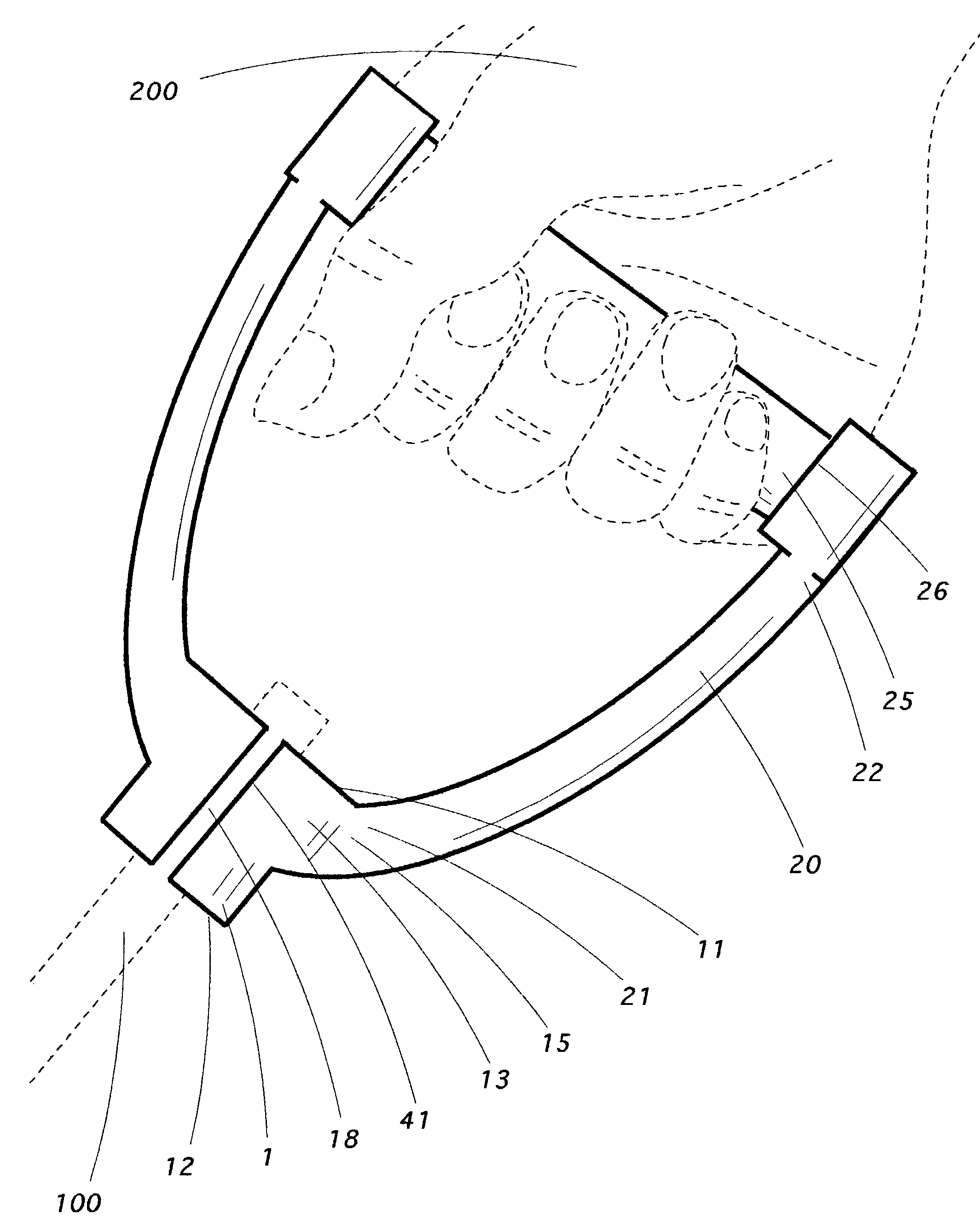
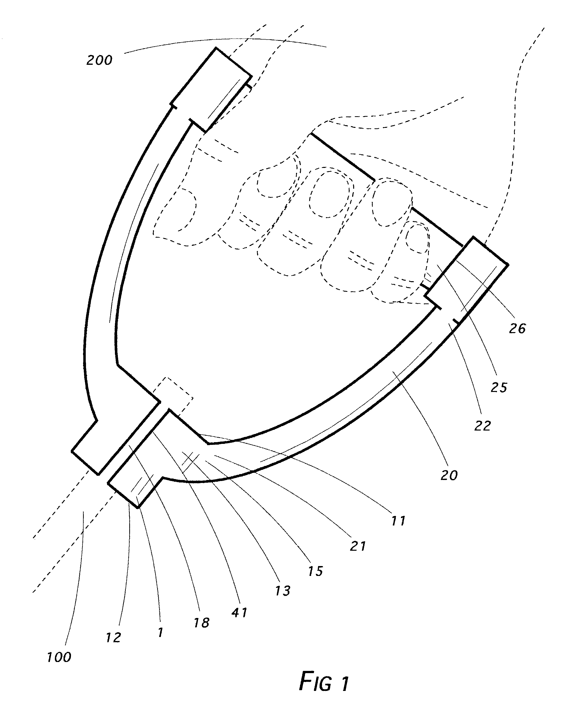
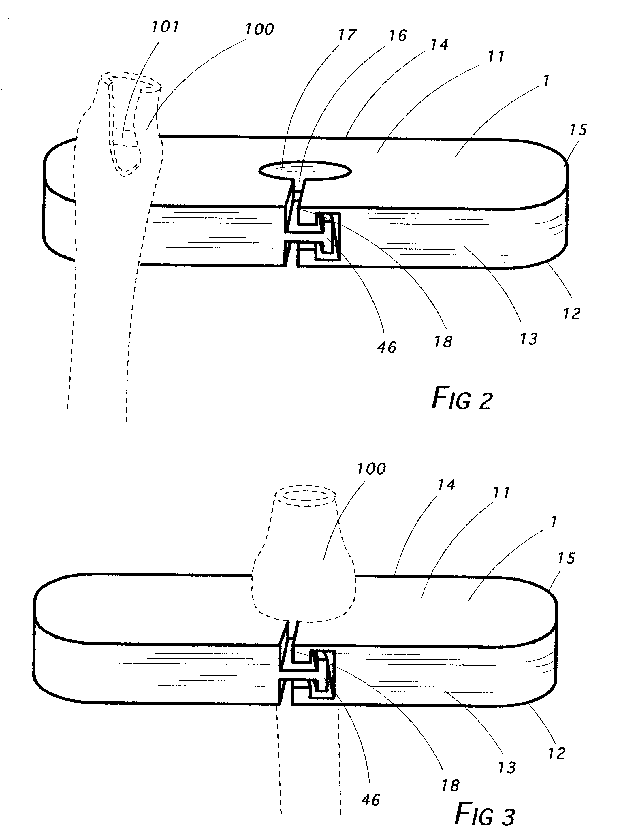
[0022]In all cases, one or more cord terminal bores (16) are present, each of which (16) allows a hollow elastic exercise cord (100) to be extended through it (16), the end of which (100) is then plugged with a stopper (101) in a manner now familiar to prior art. Each terminal bore (16) is of size such that the stoppered cord (100) cannot be pulled back through it (16) during exercise. Also in all cases, one or more cord connecting slots (18)—one for each terminal bore (16)—extending vertically across the face (13) or backside (14) of the block (1) is of sufficient depth to provide an opening with the bore (16) along the lengths of both (16, 18). Thus, one or more slots (18) might be disposed upon the face (13) and one or more thereof (18), upon the backside (14). Moreover, all of the cord connectin

Problems solved by technology

Of course, knotting was always a possibility but provided interchangeability inconvenience.
Thus, it was soon observed that while the stoppers (101) were acceptably secured in place, cord (100) interchangeability was not practically feasible.
If a number of cords (100) were to be connected to any one of a number of representative handgrips (850) for simultaneous use, the task becomes even more difficult.
It was only a matter of time, however, that some degree of dissatisfaction arose over elastic cord (100) interface with intermediate connection hardware.
Yet, even the larger bore was not without its problems—loss or misplacement of the impinging body, for example.
A review of the prior art readily reveals that the needs and objectives which have arisen have not thus far been realistically met.

Method used


Image

  • Multiply slotted exercise handgrip
  • Multiply slotted exercise handgrip
  • Multiply slotted exercise handgrip

Examples


Embodiment Construction

[0043]The subject of this application comprises a slotted exercise handgrip disposed in various embodiments, each comprising in chief a cord anchor block (1).

[0044]The cord anchor block (1) is configured with a top (11) with oppositely disposed bottom (12); a face (13) with oppositely disposed backside (14); and opposing ends (15). The block itself (1) may be shaped in simple rectilinear bar form as shown in FIGS. 2, 3, 7, 9, 10, 18 and 19. FIGS. 1 and 8 are considered for purposes of this application to comprise the bar structure, although in those two instances, each is also equipped with handgrip prongs (10) and a gripping pin (25).

[0045]For ergonomic gripping convenience, the anchor block (1) may be curved to fit one's hand and comprise flattened ellipsoidal (88) or any other convenient configuration, including a banana shaped one (89). When the block (1) is integrally made part of a solid handgrip disposed in the form of a loop or stirrup (150), discussed ante, in which attache...


PUM


Abstract

An anchor block having within it one or more tunnels through which exercise cords are run and an equal number of slots connected to the tunnels, each slot extending from either the face or the backside of the block. In certain cases, some of the slots may extend from the face while others do so from the backside. In other cases, to enhance strength, all of the slots extend solely from the face or from the backside. This slotted arrangement is useful for a solid handgrip, strapped handgrip assembly, ankle exercise cuff assembly or anchoring door impingement assembly so that stoppered elastic exercise cords may be quickly and easily interchanged. The slot may be shaped in any of several ways including straight, zig-zag or curved.

Description

[0001]This instrument, filed under 37 CFR 1.53(b) and 1.78, invoking the provisions of 35 U.S.C. 120, is a Continuation-in-Part of presently copending application Ser. No. 09 / 626,552 entitled “Slotted Exercise Handgrip”, filed Jul. 27, 2000 now U.S. Pat. No. 6,497,641.BACKGROUND OF THE INVENTION[0002]1. Field of the Invention[0003]Exercise equipment.[0004]2. Description of the Prior Art[0005]Occasionally a descriptive term in this application may be shortened so as to recite only a part rather than the entirety thereof as a matter of convenience and to avoid needless redundancy. In instances in which that is done, applicant intends that the same meaning be afforded each manner of expression. Thus, the term cord anchor block (1) might be used in one instance but in another, if meaning is otherwise clear from context, expression might be shortened to anchor block (1) or merely block (1). Any of those forms is intended to convey the same meaning.[0006]The term attach or fasten or any o...

Claims


Application Information

Patent Timeline
IPC IPC(8): A63B21/02A63B21/055
CPCA63B21/00043A63B21/0552A63B21/1403A63B21/1426A63B21/00065A63B21/0442A63B21/0557A63B21/16A63B21/1663A63B21/4001A63B21/4013
Inventor HINDS, ROBERT SYLVESTER
Owner LIFELINE PROD LLC
Learn More