Movable contact unit with operating projections, method of mounting operating projections and operating panel switch using movable contact unit with operating projections

a technology of operating projections and contact units, which is applied in the direction of movable contacts, emergency contacts, snap-action arrangements, etc., can solve the problems of increasing costs and achieve the effect of facilitating the setting of desired operating conditions

Inactive Publication Date: 2005-08-02
PANASONIC CORP
View PDF6 Cites 13 Cited by
  • Summary
  • Abstract
  • Description
  • Claims
  • Application Information

AI Technical Summary

Benefits of technology

[0016]The present invention addresses the conventional problems discussed above and aims to provide a movable contact unit with operating projections that facilitates setting of desired operating force which acts on a specified mov

Problems solved by technology

The above-mentioned examples, however, increase the variety of elements

Method used


Image

  • Movable contact unit with operating projections, method of mounting operating projections and operating panel switch using movable contact unit with operating projections
  • Movable contact unit with operating projections, method of mounting operating projections and operating panel switch using movable contact unit with operating projections
  • Movable contact unit with operating projections, method of mounting operating projections and operating panel switch using movable contact unit with operating projections

Examples


Embodiment Construction

[0050]An exemplary embodiment of the present invention is demonstrated hereinafter with reference to FIGS. 1-6.

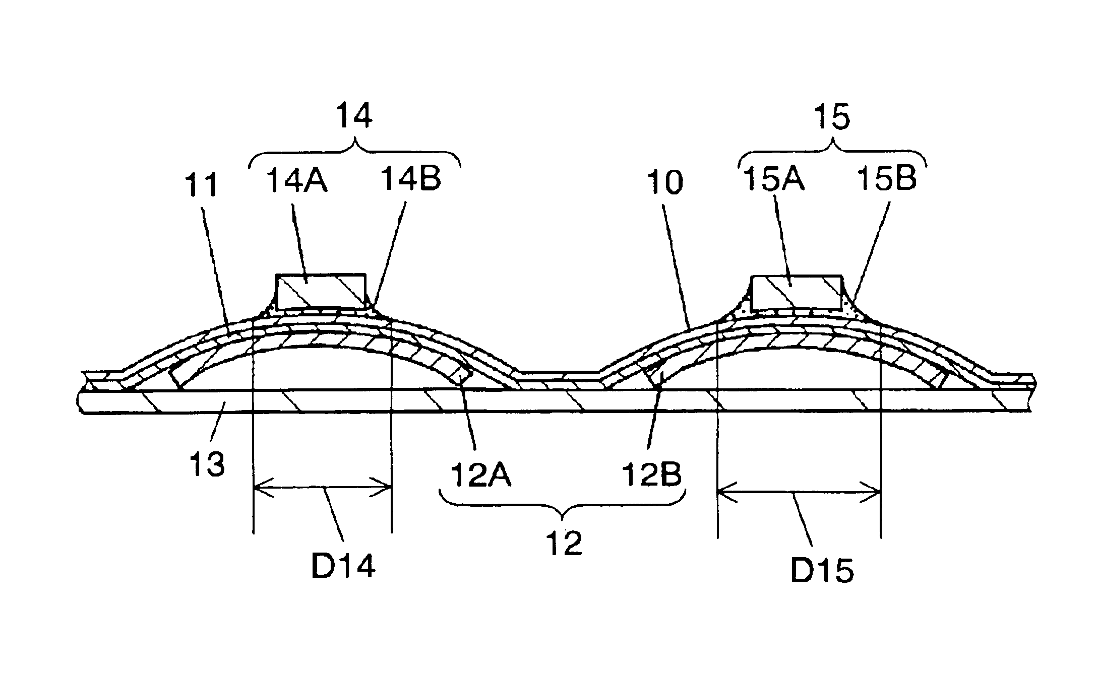
[0051]FIG. 1 is a sectional view of a movable contact unit with operating projections in accordance with the embodiment of this invention. In FIG. 1, base film 10 is a flexible film of insulating resin. Adhesive layer (second adhesive layer) 11 is formed on the whole bottom surface of base film 10, and holds top surfaces of a plurality of domed movable contacts 12 (12A, 12B) disposed in place. Separator 13 formed of a film of insulating resin is bonded to the bottom surface of base film 10 across movable contacts 12 by adhesive layer 11 to cover the whole surface of base film 10. Separator 13 is surface treated for ease of later removal.

[0052]Parts of base film 10 that correspond to respective movable contacts 12 (12A, 12B) are each formed into a shape matching the domed shape of movable contact 12.

[0053]Projecting members 14A, 15A are fixed to a top surface of base film 10...


PUM

PropertyMeasurementUnit
Fractionaaaaaaaaaa
Forceaaaaaaaaaa
Electrical conductivityaaaaaaaaaa

Abstract

Parts of a base film that correspond to respective movable contacts are formed into projections. Operating projections each including a projecting member fixed to a top surface of the base film by an adhesive resin are formed and correspond to the movable contacts, respectively. The adhesive resins have different fixed diameters.

Description

FIELD OF THE INVENTION[0001]The present invention relates to a movable contact unit with operating projections that is used, for example, in operating panels of a variety of electronic apparatuses, and also relates to a method of mounting the operating projections, and an operating panel switch using the movable contact unit with the operating projections.BACKGROUND OF THE INVENTION[0002]Recently, as portable electronic apparatuses have increased in number, a variety of electronic apparatuses have become compact and lightweight. An operating panel switch for the electronic apparatus is low-profile and affords a good click feel and an electrically stable contact, so that a so-called movable contact unit, the insulating resin film of which holds a plurality of separate domed movable contacts formed out of an electrically conductive and resilient metal plate, has found wide use.[0003]To improve operability, the operating panel switch is demanded of an arrangement of keys corresponding ...

Claims


Application Information

Patent Timeline
IPC IPC(8): H01H13/70H01H13/702H01H13/48H01H11/00H01H13/20
CPCH01H13/702H01H2205/026Y10T29/49105H01H2221/05H01H2229/058H01H2215/004
Inventor SERA, NAOKIITO, MASAHIRONUMOTO, NOBUHIRO
Owner PANASONIC CORP
Why Eureka
Try Eureka